Harley Davidson Touring: Performance Diagnostic Guide
Proper engine performance is the result of many systems working together all at once. These are the fuel system, ignition system, and all the mechanical components. Even complex, modern bikes, like late model Harleys are simple to diagnose if you follow a plan and know how the systems work together.
This article applies to the Harley Davidson Touring (2000-2014).
Intermittent engine performance problems are some of the most difficult problems to track down on your Harley Davidson Touring machine. Because so many different systems are involved, trying to diagnose the problem without testing is almost like a shot in the dark. With some specialized equipment, knowledge about each system, and a little time, even a novice can locate and correct there engines performance problems.
Materials Needed
- Multimeter
- Spark tester
- Fuel pressure tester
- Noid light
- Propane
- Basic SAE socket set with ratchet
- Rag and throttle body cleaner
- Belt deflection gauge or ruler
- Anti-seize
- Flat blade screwdriver
- T-Pin
- Liquid electrical tape
Begin your inspection by checking for diagnostic trouble codes. Often times these will lead you to the problem area. Refer to the article How to Reset Check Engine Light.
You really can't diagnose a modern fuel injected bike unless the battery is fully charged and in good condition. You can determine that and perform other electrical diagnostics with the article Electrical Diagnostic Guide.
If you are like most Harley riders, you probably have made modifications from the factory setup, which can cause tuning issues all their own. If everything checks out okay, but your bike still doesn't run quite right, you may need to add a performance tuner to it, which is covered here EFI Tuner Reivews and How-To.
Step 1 – Perform a visual inspection
The visual inspection may clue you into what area the problem is occurring. To perform the visual inspection:
- Walk around the motorcycle looking for obvious signs of damage, such as loose parts, wiring hanging from the loom, fluid leaks etc.
- Take a closer look inside and around the engine. Look for the same as above. Note any areas where fluid may be collecting on sensors and wiring, as this can create erratic readings.
- Start the engine. Listen for misfires, rough running, or smoke. Blue smoke indicates oil is making its way into the combustion chamber due to worn rings or valve seals. Black smoke indicates excessive fuel and a rich mixture due to a bad sensor reading, stuck injector or other issue.
- Listen for rattles in the bottom end. This may indicate a loose or worn primary chain, or even a bad cam chain adjuster. Primary adjustment is covered in Step 3, but if the cam chain is loose, it could spell a much more involved repair.
- Raise the RPM's to a fast idle. Does the misfire improve or get worse? Do you hear or smell exhaust coming from near the ports on the heads? This can be a sign of an exhaust leak.
- Remove and inspect the air cleaner. Refer to the article Air Intake Reviews and How-To. If the filter element appears dark, it should be cleaned or replaced. Try holding a flashlight against the air cleaner. If some of the light passes through to the other side, it is still clean enough to use. You can use compressed air and a cleaning agent to clean the filter as well. Leave the air cleaner off for Step 2 if you feel it was not your problems cause.
- Put some pressure against the spark plug wire boots. Make sure there fully connected to the spark plug. If a misfire is present, inspect the spark plug wire for arcing against metal surfaces. This is easiest to see in a dark area. Look for any wear marks on the wire and replace as needed.
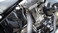
Step 2 – Inspect the intake system
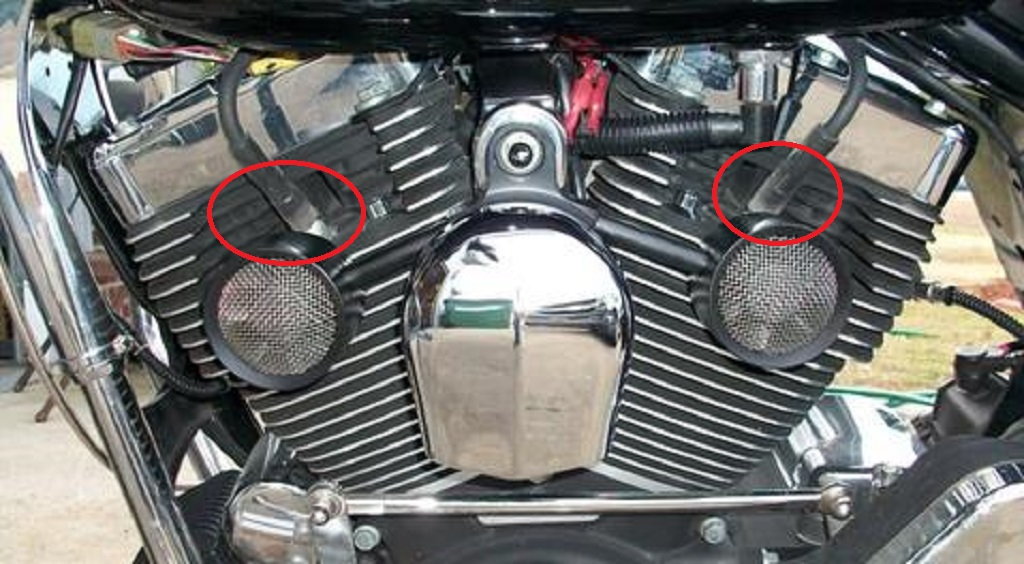
Seals and gaskets are used between the throttle body (or carburator), intake manifold, and engine. These seals maintain vacuum developed by the engine. A leak at these gaskets will draw un-metered air into the engine, reducing engine performance and often cause an erratic idle.
- With the air cleaner removed, inspect the throttle body bore and plate for dirt. Clean the throttle body and plate with a rag and throttle body cleaner. Actuate the throttle plate by hand to clean the hard to reach areas.
- Start the engine and spray propane around the throttle body and intake manifold seals. Propane is recommended for its ability to be easily extinguished if a fire develops. If the idle raises while spraying propane, the seals are leaking.
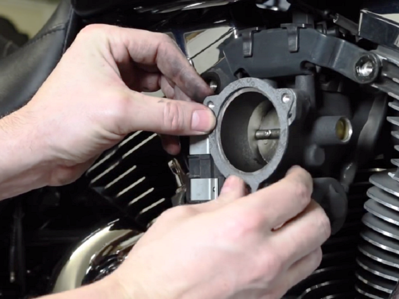
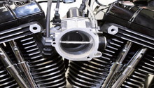
Figure 2. Replacing the throttle body gasket. 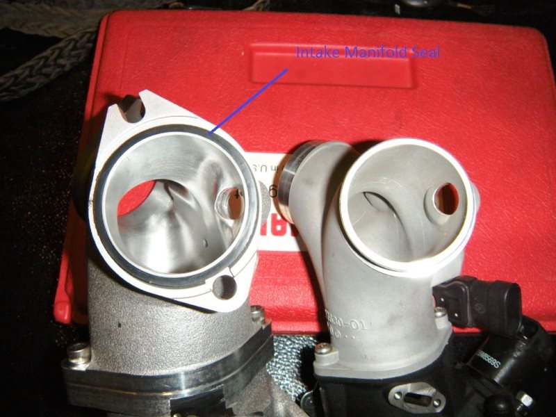
Figure 3. An intake manifold seal.
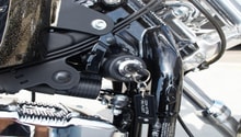
Step 3 – Adjust the drive belt and/or the primary chain
A misadjusted drive belt or primary chain may create rattles, vibrations, and hesitations. Checking for proper adjustment is part of the required periodic maintenance.
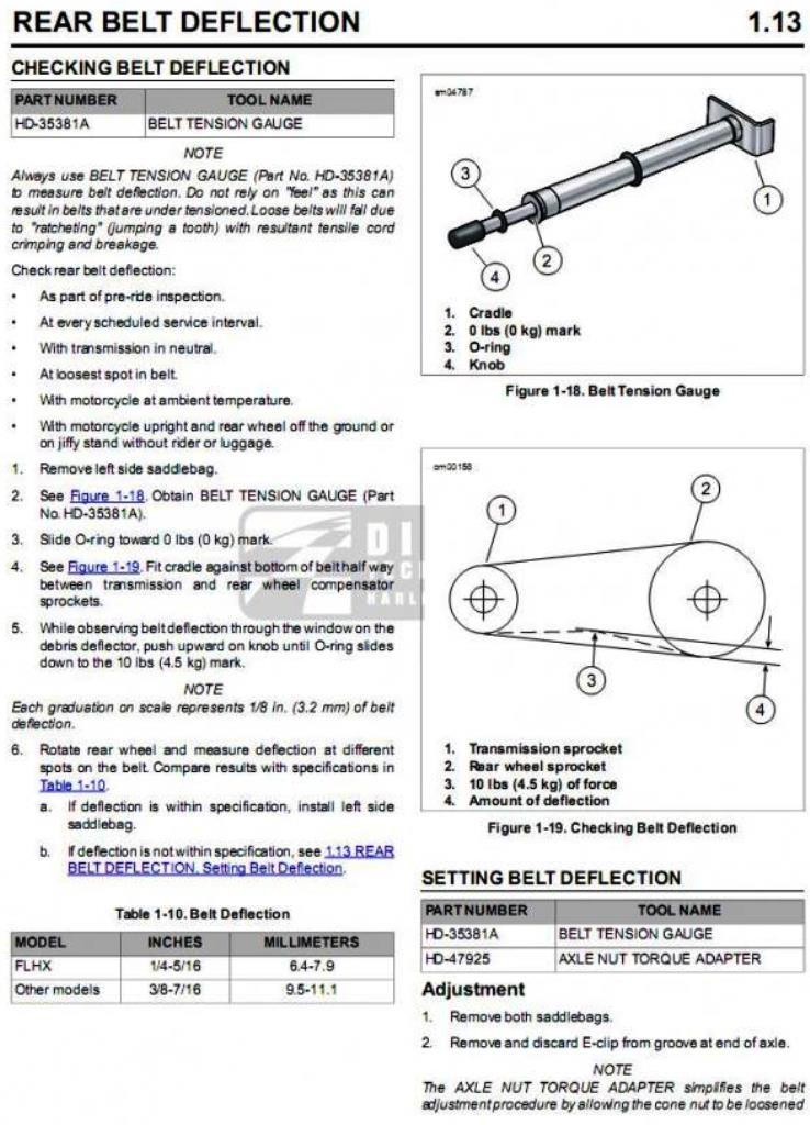
To check the belt deflection:
- Bring bike to ambient temperature.
- Set on side stand.
- Put transmission in neutral.
- 1/4" to 5/16" deflection applying a 10 lb force midpoint on the belt. ( There is a deflection window on the belt guard.)
- You can use the belt deflection gauge (HD-35381A) to make this quick and easy.
To adjust the drive belt:
- Remove the e-clip from the axle and loosen the cone nut on the right side (1 7/16" socket).
- Torque adapter #HD-47925 allows you to work between the muffler and wheel, or if you remove the rear muffler support and hang the muffler with a bungee, you can put a socket on the nut.
- Once the nut is loose, slightly snug it back up.
- The adjustment is performed on the left side of the axle. The cam on the left side is part of the axle. Turning the weld nut on the axle will rotate both cams against the stops on the swing arm, in turn moving the axle back and forth.
- Clockwise = reduce tension, Counterclockwise = increase tension.
- The belt will appear fairly tight when adjusted correctly.
- Once the deflection is correct, the axle must be torqued to 100 ft/lbs. Install the e-clip. Re-check the deflection.
- Hold the weld nut on the left side of the axle or it will turn, and the deflection will change. Applying some anti-seize between the nut and cam plate will ease the friction while torquing the nut, which will help prevent the axle from turning.
- Re-install the right side muffler support.
To check and adjust your primary chain, refer to the article Harley Davidson Softail: How To Adjust Twin Cam Primary Chain.
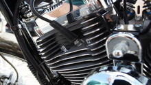
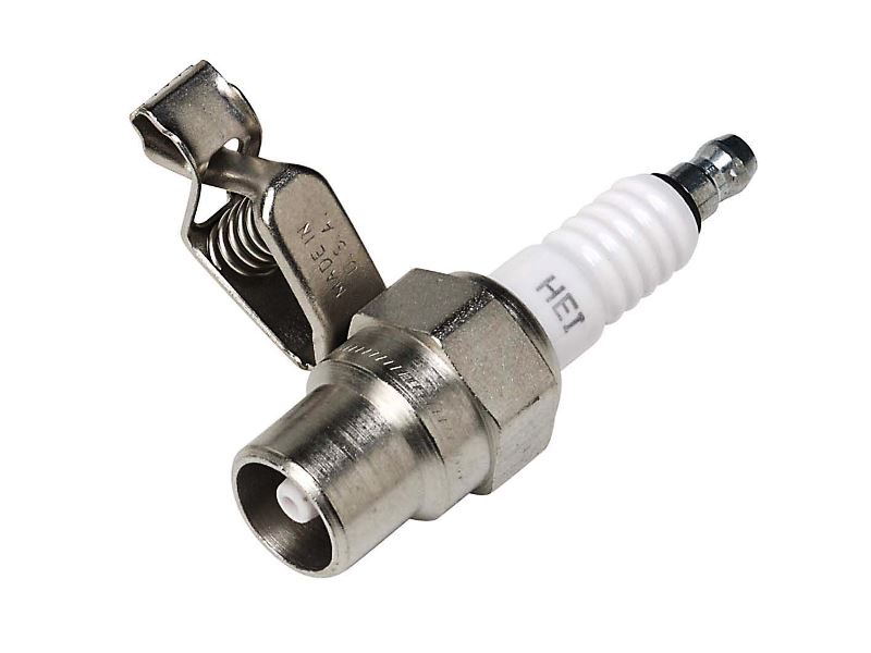
Step 4 – Test the ignition system
The ignition system uses a coil pack, spark plugs wires, and spark plugs to transfer the electricity from the battery into the engine. The engine control module uses crank sensor readings, which determine piston position to trigger the coils.
To test the ignition system:
- Remove the fuel pump fuse. It's number 17 in Figure 5.
- Crank the engine to bleed the fuel system, let it run and stall if it starts.
- Remove the spark plug wires from the spark plugs.
- Insert a spark tester into the spark plug wire and attach the tester to ground.
- Look for a consistent, strong spark at the tester.
- If no spark is present, begin checking the spark plug wires.
- If spark is present, inspect the spark plugs for cracks, damage to the electrode tip, and proper gap. Refer to your owner's or service manual for correct gap.
Check the spark plug wires by measuring the wires resistance with a multimeter. The average spark plug wire has 10,000 to 15,000 ohms of resistance for every foot of length. Inspect the ignition coil by removing the spark plugs wires from the coil.
On later model bikes:
- Remove the electrical connector from the coil. Beneath you'll see three metal prongs.
- Measure the resistance between the outer prongs and inner prong. Resistance should be between 0.5 ohms and 1.5 ohms.
- Measure the resistance between the spark plug wire posts. Resistance should be between 10,000 ohms and 20,000 ohms.
For earlier model bikes:
- Remove the spark plugs wires, power wire, and trigger wire from the coil.
- Measure the resistance between the power wire post and trigger wire post. Resistance should be between 0.5 ohms and 1.5 ohms.
- Measure the resistance between the spark plug wire post. Resistance should be between 10,000 ohms and 20,000 ohms.
The remaining component controlling the ignition system is the engine computer. It's important the computer has a constant supply of power and a good path to ground for proper operation.
To check the engine computer:
- Remove the engine computer electrical connector by pushing the connector to the right as seen in Figure 7.
- Inspect the connector and computer prongs for corrosion and bends. Clean and replace as necessary.
- Refer to your service manual or a wiring diagram online for the engine computer.
- Measure the voltage to the computer from its power supply (hot) wire. Attach the red lead to the wire and the black lead to ground. The reading should be near battery voltage.
- With the ignition on, use a t-pin to probe the power wire near the computer. Connect the red probe to the t-pin, black probe to ground. Battery voltage should be present.
- If 12 volts is not present, measure each wires continuity. A reading of OPEN or "OL" indicates a break in the wiring.
- Measuring the voltage drop. Probe the ground wire with a t-pin near the engine computer. Less than 0.5 volts should be present.
- Cover any holes created by the t-pin with liquid electrical tape.
- Repeat the continuity test for the ignition coil control wire.
- If voltage and continuity measurements are normal, replace the engine computer or have a local dealership confirm your result.
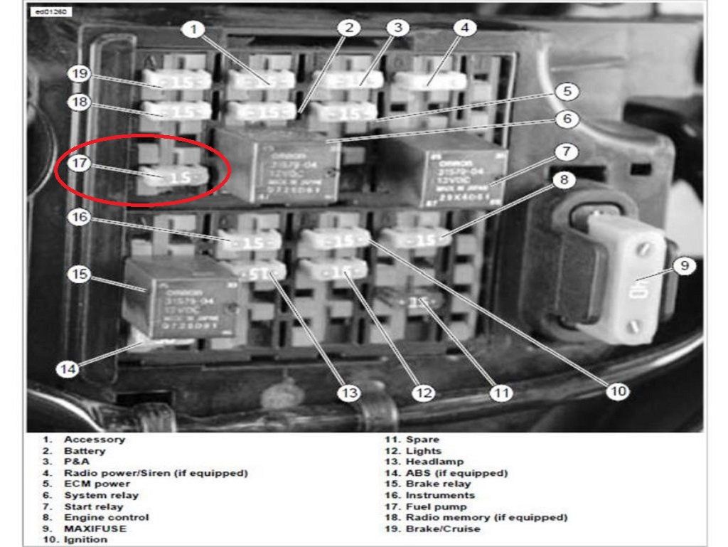
Figure 6. The fuel pump fuse. 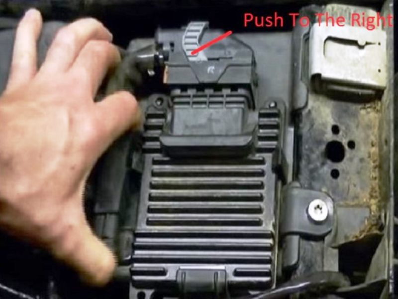
Figure 7. The engine computer.
Step 5 – Test the fuel system
The fuel system begins with the fuel pump. It pressurizes the fuel and pushes it towards the fuel injectors. The injectors receive an electric signal from the engine computer to spray fuel into the combustion chamber.
Begin checking the operation of the fuel pump by:
- Turning on the ignition and listening for the "buzz" of the fuel pump inside the fuel tank. This noise should last for several seconds.
- If no buzz is heard, check the power and ground supply to the fuel pump by referring to Steps 3 and 7 of following the article How To Replace Fuel Pump and Filter.
- If no power and/or ground are found at the connector, locate the cause by performing a voltage drop test on both wires.
- If a buzz is heard, you can check fuel pressure by following the Step 6 of the article Harley Davidson Sportster: Engine Performance Diagnostic Guide.
- Replace the fuel pump/regulator if low pressure is found.
Check the fuel injectors by:
- Start the engine.
- Feel for a clicking with your finger or listen with a mechanic's stethoscope at the injector while operating. This is the injector opening and closing normally.
- Measure the injectors resistance. Refer to your service manual or a local Harley Davidson dealer for exact resistance specifications. A reading of OPEN or "OL" confirms the injector needs to be replaced.
Check the fuel injector power and ground wires by:
- Inserting a fuel injector noid light into the injector electrical connector.
- Start the engine and watch for the bulb to flash. A consistent, bright flash indicates the injector wiring is okay.
- If a problem is present, you'll need to voltage drop test both wires.
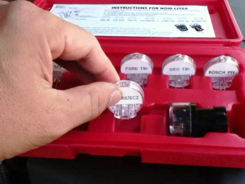
Figure 8. You can buy a complete noid light kit, but you only need the Harley light. 
Figure 9. The fuel injectors.
Related Discussions
- Checking Primary Chain - HDForums.com
- Street Glide Running Rough - HDForums.com
- Sputtering and Running Rough - HDForums.com