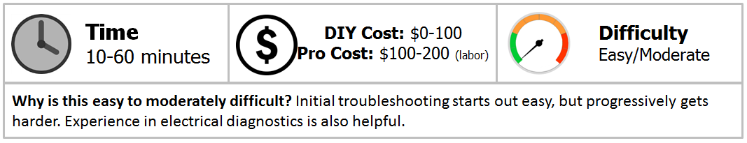
Harley Davidson Touring: No Throttle Response
In 2008, Harley Davidson implemented a throttle by wire design, eliminating the throttle cable. One of the nice advantages of this system is electronic cruise control, but this design has its disadvantages, too, such as loose connections and broken sensors.
This article applies to the Harley Davidson Touring (2008-Present)
The fly by wire equipped Touring's use a twist grip sensor, electronic throttle control actuator (throttle body), and an engine computer to determine throttle input from the rider. The connections between these components must be good for normal engine operation. A frequently occurring problem was found with early throttle by wire system and a Technical Service Bulletin (TSB) was released. This bulletin guides you through the diagnostic steps to determine what connection or component is creating your throttle problem.
Materials Needed
- Multimeter
- T-pin or similar probing tool
- Dielectric grease
- SAE socket set with ratchet
Step 1 – Check for diagnostic trouble codes
A diagnostic trouble code will help pinpoint the problem area. To check for diagnostic trouble codes, read the article How To Reset Check Engine Light. Codes that are often present when a problem in the throttle by wire system is detected are:
- P0120
- P0220
- P0122
- P0123
- P0222
- P0223
Record any present codes, erase the codes and continue to Step 2.
Step 2 – Reset the ECM/limp mode
Limp mode occurs when a system on your Touring is unable to provide enough information to the engine computer for proper operation. Limp mode acts as a back-up to keep your Touring drive-able while a problem is present. Limp mode is a common occurrence during throttle by wire problems. Your Touring is most likely in limp mode if:
- The throttle is unresponsive, or
- engine RPM'S drop to 1500.
Sometimes, an ECM reset will restore normal operation. To reset your ECM, read the article How To Reset The ECM. Another option is to remove the negative (black) battery cable for five minutes. With normal operation restored, you can safely drive your Touring back home or to a dealer or shop.
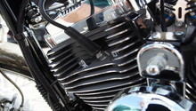
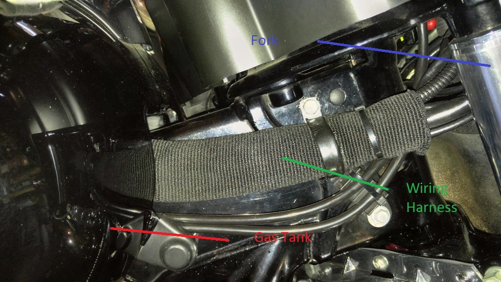
Step 3 – Check wiring between gas tank and backside of faring
There is a zip tie between these two components that secures the wiring harness to the frame. The zip tie has been known to not allow enough travel when the handle bars are fully turned. In effect, the wiring breaks as it's being stretched and rubbed by the zip tie.
Locate the zip tie between the gas tank and backside of faring. Rotate the handle bars and ensure the wiring harness is not being pulled during the full range of motion. If it is, remove the zip tie and install a looser fitting zip tie. Inspect, replace and/or re-connect the wiring as needed.
Step 4 – Troubleshoot according to TSB TT418A
This Technical Service Bulletin applies to 2008 and newer Touring models. It covers the procedures to inspect and test the systems that commonly cause little or no throttle response. You can read the entire TSB here, or click over to the Harley website and look up recalls and TSBs for your bike based on the VIN here. Briefly, here is what it says:
Throttle Position Sensor (TPS) circuit DTC's P0120, P0220, P0122, P0123, P0222 and P223 should take diagnostic priority over a P2135 code. If any of these TPS codes exist concurrently with the P2135, they should be investigated first using the diagnostic manual.
P2135 - The Throttle Control Actuator has two potentiometers (designated as TPS1 and TPS2) and a electric DC motor for controlling the actuation of the throttle. The two TPS sensors work opposite of each other; TPS1 voltage ranges from 0.0-5.0 Volts, while TPS2 voltage ranges from 5.0-0.0 volts. The sum of the two TPS voltages should always measure approximately 5.0 volts. TPS1, pin # 37 (Brown/Violet wire) of the ECM, and TPS2 pin #36 (Brown/Red wire) of the ECM.
With the connectors plugged in to the TCA and the ignition on, probe the brown/violet wire on sensor 1. Use a t-pin or similar tool to make contact with the wire. Set your meter to D.C. volts and read the voltage while moving the throttle actuator plate manually. Repeat the same test for sensor two.
Corrosion is a major contributor of this problem. A poor connection at the Throttle Control Actuator (TCA) can also affect the sensor voltages.
Repair Procedure:
- Wiggle the TCA [211] and the ECM [78] connectors. Measure the voltage at each sensor.
- If the voltage changes while wiggling the ECM connector, replace the affected ECM terminals (part # 72605-08).
- If no voltage change is noted while moving the ECM connector, the connection issue could be in the TCA. Replace all socket terminals with NEW terminals (part # 72663-11, used in current production).
- BEFORE CONNECTING the TCA CONNECTOR, clean the male TCA pin terminals with a swab and alcohol, and ASSEMBLE WITH DIELECTRIC GREASE.
DTC P2101 - Each TPS supplies input to the ECM in response to the position of the throttle plate. The ECM activates the motor in the TCA to move the throttle plate, based on signals from the Twist Grip Sensor (TGS). When the ECM send voltage to pins 2 and 3 of the TCA to move the throttle motor, it checks for TPS1 and TPS2 voltage changes. If it does not sense TPS changes, it will set this code.
Verify that the throttle plate moves freely when engine is not running. If it does not, the TCA needs to be replaced.
Poor ECM connections seem to be the most likely cause and may be aggravated by the seat pan making contact with the ECM connector. Often, this is due to the installation of an aftermarket seat. It may be possible to cut out a portion of your seat above the ECM connector to prevent contact.
A poor connection at ECM pins #29 and 30 could cause an interruption in voltage to the throttle motor and set this code. The ECM uses voltage from pin #52 yellow/green wire to supply power at pins #29 and 30, causing the same symptoms.
Repair Procedure:
Identifying the connection issues at this location may be difficult.
- Replace all socket terminals with NEW terminals (part #72663-11 used in current production) at the TCA connector [211B].
- BEFORE CONNECTING the TCA CONNECTOR, clean the male TCA pin terminals with a swab and alcohol, and ASSEMBLE WITH DIELECTRIC GREASE.
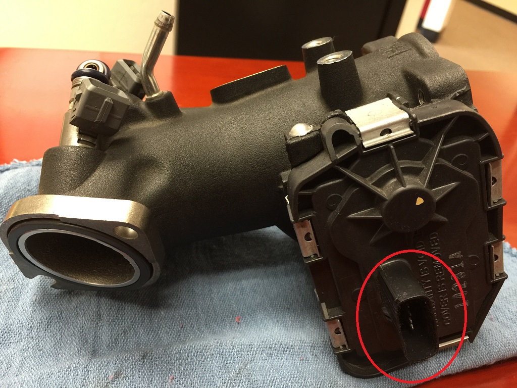
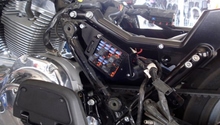
Figure 2. The throttle body sensor pins. 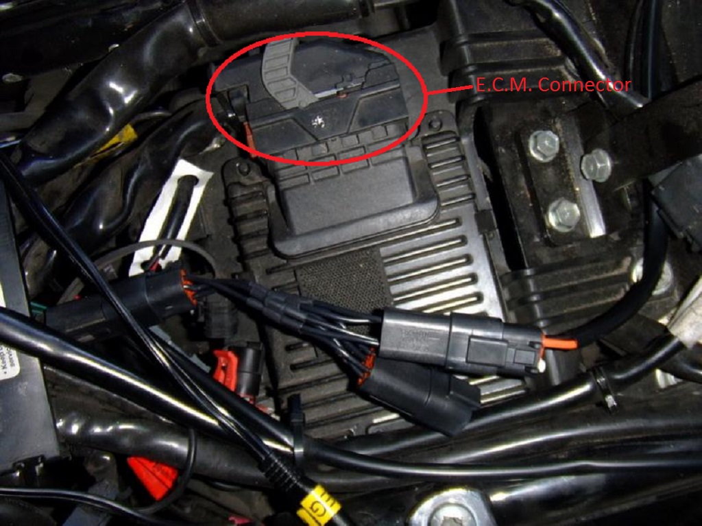
Figure 3. Push the gray handle to the right to remove the connector from the ECM.
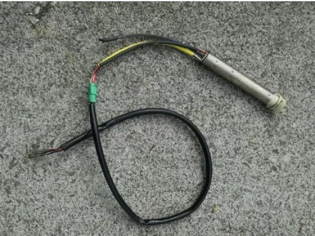
Step 5 – Inspect and test the twist grip sensor
The fly by wire Touring models use a sensor in the right handle bar grip to measure twist grip movement. To access the sensor, you'll need to disassemble the right handle bar grip. Read Step 6 of the article How To Install Handlebars for twist grip removal.
With the twist grip removed, you'll see a green connector. Unplug the connector and measure the resistance between the gray and red wires. Do the same for the black and brown wires. A reading of OPEN or "OL" indicates the twist grip sensor needs to be replaced.
If the resistance reading at the twist grip sensor is normal, make sure continuity is present throughout the wiring's path to the ECM by measuring at these points:
- Black/grey wire at female connector on twist grip sensor to black/grey wire on ECM (pin 62).
- Violet and yellow wire on twist grip sensor to violet/yellow wire on ECM (pin 39).
- Red/white wire on twist grip sensor to red/white wire on ECM (pin 68).
- Black/white wire on twist grip sensor to black/white wire on ECM (pin 61).
- Blue/green wire on twist grip sensor to blue/green wire on ECM (pin 59).
- Brown/orange wire on twist grip sensor to brown/orange wire on ECM (pin 50).
If the reading Open or "OL" is present on any of these six wires, there is a break in the wiring.
Related Discussions
- Fly by Wire Throttle Failure - HDForums.com
- No Throttle Response - HDForums.com
- Word of Warning for 2010 Touring Bikes - HDForums.com