
2012 Street Glide Ape Install Tutorial
#1
 03-21-2012, 06:17 PM

First of all, I know I'm no professional mechanic. I don't pretend to be. This tutorial is made for average people who want to install their own bars and cables. There may be some better ways to do some of the things I have done. If so, please post them. When I started this project, I tried to find a good tutorial to help me. I found some. I wanted to try to make it more complete. I'm not trying to say other people's post were not good enough. I'm just trying to add to what is already posted here. Ok, now that the disclaimers are done let's get to the tutorial. Please know I made plenty of mistakes, but at the end everything works fine..... .
.
Tools Needed:

Here is what I started with. I used a 4 inch 5/16 stainless bolt, stainless washer, nylon bushing, and 5/16 plastic ****. I purchased all of this from my local Ace.
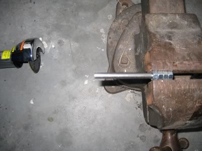
I used nuts to protect the threads and cut off the head of the bolt. you will need the whole length of the bolt for this to work. I probable should have used a 4.5 inch bolt.

I used a torch and heated the bolt and hammered it with a 3lb hammer until I got it to make the original ignition switch.

Here is the finished tool. I had to drill out the nylon bushing a little. It was used to protect the inside of the ignition switch. I used blue locktite on the theads for the ****. It works perfectly.
The next post with be the start of the project.
Tools Needed:
- Homemade, or store bought, ignition tool
- various sockets..(hex, star... long and short.. get the hex with the rounded head, star)
- in/lb torque wrench (mine are CDI Torque made by SnapOn)
- ft/lb torque wrench (mine are CDI Torque made by SnapOn)
- Service Manual - (Very important.. You should get one as soon as you buy the bike)
- split ring tool (trust me you will need it)
- of course various sizes of screw drivers
- Did I say service manual...
- plenty of old towels to wrap painted parts
- new clutch release cover gasket (it's only $5.00)
- New tranny fluid (I used Spectra)
- New brake fluid (Mine uses DOT4)
- Different sizes of extensions (I used heat shrink on all of my extensions and ratchets... worked great to protect from banging against the bike)
- Soldering Station (I bought a Weller WDC100.. If you are going to solder. Some people like the plug and play extensions, but I prefer a solid connection.. Just me though)
- Plenty of heat shrink tubing in various sizes (I bought mine at Harbor Freight)
- Helping Hands to hold the wires (also purchased at Harbor Freight)
- various colors of 18 or 16ga. wire (I purchased mine from my local Ace Hardware. They sell it in feet)
- Cordless Drill ( I only needed this to put a dimple in the handle bars for my Performance Machine XL grips.. They have set screws)
- A motorcycle jack helps
- Did I mention the Service Manual... I can't remember if I did...lol
Here is what I started with. I used a 4 inch 5/16 stainless bolt, stainless washer, nylon bushing, and 5/16 plastic ****. I purchased all of this from my local Ace.
I used nuts to protect the threads and cut off the head of the bolt. you will need the whole length of the bolt for this to work. I probable should have used a 4.5 inch bolt.
I used a torch and heated the bolt and hammered it with a 3lb hammer until I got it to make the original ignition switch.
Here is the finished tool. I had to drill out the nylon bushing a little. It was used to protect the inside of the ignition switch. I used blue locktite on the theads for the ****. It works perfectly.
The next post with be the start of the project.
Last edited by murph; 03-22-2012 at 01:35 PM.
#2
03-21-2012, 06:42 PM


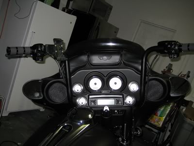
The first two photos are of the bike stock.

Here the bike is strapped down on the lift. with tank, side covers, seat and bags removed. easy so far... but it gets a little harder.

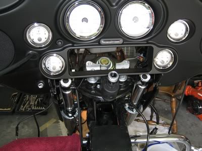
A photo of the inside of the fairing prior to me playing Dr. Frankenstein...lol

The radio is removed. It too a long rounded hex key socket to remove the radio. I took the radio out through the backside. Be careful with the ignition switch. I though I had to remove the wire in the back and ended up braking the very fragile tab in side holding the main three wire going to it.. That was a $60.00 mistake.. Ouch...lol There is a small nut on the top of the ignition switch. I used an adjustable wrench to remove it. There are two small screws on the side of the ignition cover and it came off easy.

In the middle of this photos are the wire going into the ignition switch... That I DID NOT need to remove....

Here are two photos with the bars removed. I made another mistake here. I did not loosen the riser bolts with the bars on... That took a little while to fix. (to replace stock bushings with the new nylon ones). I loosened the inner fairing so I could move it a couple of inches each way to access the hand bar clamp bolts a little easier. (remember, you really need the service manual for this whole project).
More to come.
#4
03-21-2012, 06:51 PM

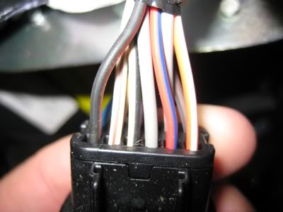


Here are some photos of the wiring inside of the fairing... I can not emphasize how important the service manual is for this project. It helped me a lot. Also, take plenty of photos of the wire. I only posted a couple.. I actually took about 15-20 at different angles. It will help when you take everything apart. I made a drawing of each connector with labels also.


Here is where I took off the connectors. I used a small pair of needle nose pliers to pull the inner locking guide out. You only need to move it out about an inch. It will pop loose when you pull on it. DO NOT remove it completely. It is only suppose to come out to make it possible to remove the wire from the back side. I used a modified paperclip to push in to release the wires. This process took a little while to get the hang of it. Once to get the feeling of it after a couple of wires it gets easier.
#5
03-21-2012, 07:09 PM
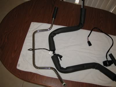
Here is the original bars next to my new WO576 (14" bagger apes).


This is the right (TBW) side pulled through the bars. I was able to use the original TBW wire and housing wires with no splicing inside of the bars. I did not need to extend the TBW, but I had to extend the other wires. I had a Weller WLC100 soldering station with a set of helping hands to do the soldering. It helped. I got the helping hands from Harbor Freight for a couple of bucks.

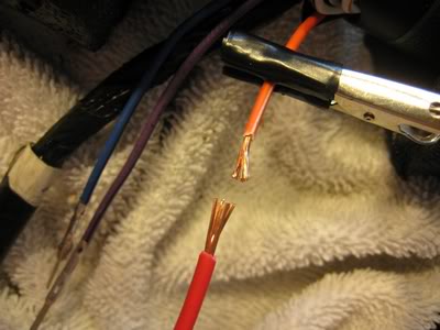
I did not twist my wires. I separated each individual wire in a fan shape and then pushed them together. I always use flux. (thats the brown goo on top of wire). I used shrink wrap for each wire. I made sure there was no small spikes in the solder to make sure it did not poke through the heat shrink.

Here is a photo of some of the wires after I soldered the extensions.

Here is a photo of completed wiring extensions. I used larger heat shrink to cover the wires after I finished the extensions. I pulled and extra two wire on the left side just in case I need to add anything. I also pulled an 1/8" 8' long stereo wire through the left side for my Garmin Zumo 500. Just in case I wanted to connect my Garmin to my stereo later. Or use earphones.... I doubt it, but it is there just in case. I also had to pull the power wire for the Garmin.. The wire pulling was not too bad. I used a large 12 gauge wire and taped it to the original ones and used Dawn soap.. Worked great. I might have bubble coming from my bars for awhile, but it was worth it.
Last edited by murph; 03-21-2012 at 07:43 PM.
#6
03-21-2012, 07:40 PM
Ok. I did not take a photo of the bars after I installed them. I forgot because I was so tired. Having the inner fairing loose helped with installing the new bars. It would also help you to have plenty of sockets and socket extensions that allow the sockets to move. Not everything works in a 90 degree angle.
I bought Magnum clutch and brake cables... upper and lower.
The next step I worked on the clutch cable. the transmission drain plug in on the bottom of the pan located towards the front on the right side. Drain the fluid. Make sure you have replacement fluid and new gasket on hand. Many people told me I could use the original gasket, but for $5.00 why take a chance.
I forgot to loosen the cable at the clutch release cover. I had to reattach it to do this. Helpful hint there. In the service manual, it tells you to remove the exhaust. I just removed the heat shields.. Again, this is where having sockets that work at multiple angles help. Just in case your forget to check, the two smaller bolts go in the two top hole.
When you get the cover off, you do not have to disassemble the inside. I just twisted the cable 180 degrees so the holding clamp inside was turned upside down. it has a flat side which lets it to be removed. When you go to put the cover back on, refer to the service manual for tightening pattern and torque values.
The next step was the brake lines. The master cylinder line goes through the fairing and along side of the back bone under the gas tank to the ABS module located on the right side of the bike behind the right side cover. The caliper lines come from the ABS module to the distribution block located under the triple tree and to each caliper. I tried to keep air out of the line, but it is pretty much impossible. I know one of the mechanics at my local dealer... He is a good guy and only tells things I need to do at the dealer. I STRONGLY suggested... **** , told me to bring my bike into the shop to have the ABS serviced after I installed and manually bled the lines. I trust him. He stated the warranty will not cover the ABS module if you change the brake lines and do not have the dealer do the service on the ABS module. It costs me about $100.00 to have it done... But it is better than $450.00 for a new ABS module... The choice is up to you, but for me... no choice. I trust him. Anyways, replacing the brake lines were pretty simple. I used a vacuum brake tool I purchased from Harbor Freight and two 60cc syringes I got from Tractor Supply. One to pull the fluid and one to push... Remember, newer bikes take DOT4 fluid. I kept a bottle of windex to wipe down and spills as soon as it happened.
I had to use my Dremel tool to cut out a channel for the stereo wire and power wire for my Garmin in the switch housings on the left side. I just took my time. I also painted the part of the bars the switch housing and grips attach to.. it came unpainted and started to rust. Because I used Performance Machine Contour XL grips, I did not have to worry about clearance. The left grip uses two set screws to hold it in place... Really nice grips. I love them.
A friend of mine, Ron, took a piece of aluminum plate and cut a small square piece to mount my Garmin on the left switch housing. I used two aluminum spacers and longer bolts I purchased from Ace. I cleaned everything with brake cleaner, painted with automotive etching primer, and then painted with flat black automotive paint. Looks great to me.

Here is a photo before a finished assembly. All wires worked perfectly. You may have to play with the routing for the clutch cable. I ordered +8 on mine. It work okay for my WO576 bars.
Okay here is the finished photos. I hope this tutorial helps someone out. If I remember anything I will post or modify the original posts. If anyone thinks I need to add anything, please let me know...

Okay... you can post now... Thanks for waiting...
Oh, I forgot to add that I tested everything and it seems to work great.
I bought Magnum clutch and brake cables... upper and lower.
The next step I worked on the clutch cable. the transmission drain plug in on the bottom of the pan located towards the front on the right side. Drain the fluid. Make sure you have replacement fluid and new gasket on hand. Many people told me I could use the original gasket, but for $5.00 why take a chance.
I forgot to loosen the cable at the clutch release cover. I had to reattach it to do this. Helpful hint there. In the service manual, it tells you to remove the exhaust. I just removed the heat shields.. Again, this is where having sockets that work at multiple angles help. Just in case your forget to check, the two smaller bolts go in the two top hole.
When you get the cover off, you do not have to disassemble the inside. I just twisted the cable 180 degrees so the holding clamp inside was turned upside down. it has a flat side which lets it to be removed. When you go to put the cover back on, refer to the service manual for tightening pattern and torque values.
The next step was the brake lines. The master cylinder line goes through the fairing and along side of the back bone under the gas tank to the ABS module located on the right side of the bike behind the right side cover. The caliper lines come from the ABS module to the distribution block located under the triple tree and to each caliper. I tried to keep air out of the line, but it is pretty much impossible. I know one of the mechanics at my local dealer... He is a good guy and only tells things I need to do at the dealer. I STRONGLY suggested... **** , told me to bring my bike into the shop to have the ABS serviced after I installed and manually bled the lines. I trust him. He stated the warranty will not cover the ABS module if you change the brake lines and do not have the dealer do the service on the ABS module. It costs me about $100.00 to have it done... But it is better than $450.00 for a new ABS module... The choice is up to you, but for me... no choice. I trust him. Anyways, replacing the brake lines were pretty simple. I used a vacuum brake tool I purchased from Harbor Freight and two 60cc syringes I got from Tractor Supply. One to pull the fluid and one to push... Remember, newer bikes take DOT4 fluid. I kept a bottle of windex to wipe down and spills as soon as it happened.
I had to use my Dremel tool to cut out a channel for the stereo wire and power wire for my Garmin in the switch housings on the left side. I just took my time. I also painted the part of the bars the switch housing and grips attach to.. it came unpainted and started to rust. Because I used Performance Machine Contour XL grips, I did not have to worry about clearance. The left grip uses two set screws to hold it in place... Really nice grips. I love them.
A friend of mine, Ron, took a piece of aluminum plate and cut a small square piece to mount my Garmin on the left switch housing. I used two aluminum spacers and longer bolts I purchased from Ace. I cleaned everything with brake cleaner, painted with automotive etching primer, and then painted with flat black automotive paint. Looks great to me.
Here is a photo before a finished assembly. All wires worked perfectly. You may have to play with the routing for the clutch cable. I ordered +8 on mine. It work okay for my WO576 bars.
Okay here is the finished photos. I hope this tutorial helps someone out. If I remember anything I will post or modify the original posts. If anyone thinks I need to add anything, please let me know...
Okay... you can post now... Thanks for waiting...
Oh, I forgot to add that I tested everything and it seems to work great.
#7
03-21-2012, 08:51 PM
Cruiser
Join Date: Mar 2011
Location: Royal Oak, MI
Posts: 240
Likes: 0
Received 0 Likes
on
0 Posts
Trending Topics
#8
03-22-2012, 08:22 AM
It's not an impossible job. Just take your time. After this one, I'm way more confident I could do this job in one day.
Send me a PM if you want to talk in person about this. Many people on this forum helped me out a lot. They listened my questions and talked me through it. It's my turn to do the same for others.
#9
03-22-2012, 08:36 AM
Murph,
Great write up!
I've got the same Bars on my Ultra and love them.
When I did mine, I removed the entire inner Fairing, it was a little more work, but it really gave me a lot of room to manuever.
And, I made the same $60.00 mistake you did with the little plastic tab breaking on the bottom of the ignition switch. I think Harley designs them to break so they can sell new switches
#10
03-22-2012, 08:39 AM
Ultimate HDF Member