
Another license relocation question: led polarity in license plate
#1
 01-12-2012, 01:43 PM

Hi,
I have a 97 Road King and I've purchased a 2009 turn signals with the integrated light inside. It's the part number 68742-09 and I think this is used by the Ultra Classic models.
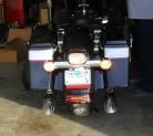
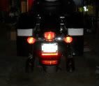
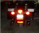
The turn signals bar fits perfectly and the hole matches with my 97 holes so, this is great. The connectors for both turn signals are the same and it should be a plug and play thing. Great too. I have relocated the fender tip connector to give power to the license plate light but...
The bar that I've bought doesn't come with the connector in the license plate light and both cables are black so, I don't know which one is the + and which one goes to the ground.
Both cables get soldered into the light and in the circuit one goes marked T1 and the other T2. I really don't know if this will help me in any way.
So, what do you think? How can I know how to wire them?
I put a link to my Picassa Album where there are the photos of the turn signal bracket, license plate lights, etc. The pics are here:
https://picasaweb.google.com/javiere...eat=directlink
Hope that someone can help me. Thank you very much.
I have a 97 Road King and I've purchased a 2009 turn signals with the integrated light inside. It's the part number 68742-09 and I think this is used by the Ultra Classic models.
The turn signals bar fits perfectly and the hole matches with my 97 holes so, this is great. The connectors for both turn signals are the same and it should be a plug and play thing. Great too. I have relocated the fender tip connector to give power to the license plate light but...
The bar that I've bought doesn't come with the connector in the license plate light and both cables are black so, I don't know which one is the + and which one goes to the ground.
Both cables get soldered into the light and in the circuit one goes marked T1 and the other T2. I really don't know if this will help me in any way.
So, what do you think? How can I know how to wire them?
I put a link to my Picassa Album where there are the photos of the turn signal bracket, license plate lights, etc. The pics are here:
https://picasaweb.google.com/javiere...eat=directlink
Hope that someone can help me. Thank you very much.
Last edited by Javieret; 01-12-2012 at 01:58 PM.
#2
01-12-2012, 02:22 PM

T1 is probably +.
look on the wire for a white stripe, if there is a mark, that is +.
other wise, just test it- you can use a 9 volt battery if you have one at hand, other wise, just touch the wires to the battery in the bike, and note which way makes the leds, light.
you cannot hurt it by testing it the wrong way around
once you know the polarity, you can splice into the "run" light circuit
Mike
#3
01-12-2012, 02:39 PM
#4
01-12-2012, 09:18 PM
#5
01-12-2012, 09:31 PM
Road Warrior
I didn't like the Bullet Turn Signal bar used my my '09 Road Glide. But loved the "Full Bar" look of the Road King. So I bought the Road King bar and LED light. When i got them home, I, also, found the wires not marked. What I did was, before I inserted the wires in the plug housing, I plugged the wires in the tail light housing. I checked to see what was the correct polarity and had light. I marked the positive lead and installed them in the plug. I then put the Turn signal bar together and plugged the wires in the tail light.
Everything worked and I love the Full Bar look. Rear Facsia installed . Running Lights on . . Brake Lights on ....
I just installed the Street Glide Fascia. I ran the LED Brake/Running light under the seat and plugged it into the Tour Pak Plug. I am making a splitter plug to be able to still use the Tour Pak Lights.
Last edited by Ultra89Rider; 01-13-2012 at 03:06 PM.
#6
01-13-2012, 04:34 AM
Well, as I said before, the led lights work without knowing which wire is the positive and which one is the negative.
A friend of mine (who is an electrician engineer) has explained me why is this so and I would like to share with you.
The license plate led lights works because they have an integrated Graetz circuit, that basically is a 4 diodes bridge that solves the polarity problem. If you want to know more about this, this is the wikipedia article that explains more what is a Graetz bridge.
http://en.wikipedia.org/wiki/Diode_bridge
Thank you very much for your help and best regards.
#7
01-14-2012, 10:50 PM
Just thought I'd add this for anyone interested.
A Diode in an electrical circuit is the equivalent of a "check valve" in a pipe system. A diode only allows electricity to flow in one direction. Electricity flows from -ve to +ve. To test if a diode is good all you do is put an ohm meter on the terminals and if it shows no continuity with the probes on terminals one way and continuity with the probes reversed the diode is good. Anything else would be a bad diode. Knowing this you can tell -ve terminal from +ve by placing the "red" +ve & black -ve probes from the Ohm meter on the terminals of the diode. If no continuity show switch the probes and you should get continuity. Once you have continuity you now know the terminal with the black probe on is -ve and the other one is +ve.
If a LED is backwards in a circuit and no other components such as a bridge are added to the circuit the LED will NOT emit any light. Also if hooked up backwards unless grossly over powered no harm will be done to the LED. Just reverse the connections.
I won't get into the use of "Diode Bridges" which have many uses and differences when used with AC vs DC electrical currents.

Thread
Thread Starter
Forum
Replies
Last Post
joshag
Sportster Models
0
04-15-2018 05:10 AM
xracer110
Electrical/Lighting/Alarm
2
12-02-2012 07:15 AM