
Street Glide LED mod with Pics
#1
 03-31-2009, 10:00 PM

Bigmeanie (Todd) posted recently about a mod to the stock SG facia LED, replacing the stock circuit board that has four LED's with three flexible strips of 30 LED's from Custom Dynamics. Here's Todd's original thread:
https://www.hdforums.com/forum/touri...mods-done.html
The short version of this project is: (1) heat the seam between lens and housing and pry them apart to separate the two pieces; (2) remove the stock LED circuit board; (3) break-off and grind down the brackets in the roof of the housing; (3) install the three LED strips from Custom Dynamics; (4) seal the hole in the housing and attach the lens to the housing with RTV silicone; and, wire the LED for run/brake light functions.
I spoke to Todd about the change and decided to give it a try because I was considering the HD accessory LED that replaces the stock run-only light function with the one that provides run and brake light functions.
Along the way, I changed from what Todd did only with respect to mounting the LED strips which I will explain below. It's a pretty simple project and, for me, worthwile.
Step 1--Separating the lens and white housing.
Removing the LED from the facia involves unplugging the electrical connector and two torx screws that secure it to the facia.
Take a hair dryer and heat the seam between the lens and white body of the light. Use a pick tool, small flat blade screwdriver, then larger flat blade screwdriver to separate the lens from the white housing by prying them apart. The lens is held in the white housing with a rubber/latex sealant, so heating the seam loosens the adhesion and allows the lens to be separated from the housing. Don't worry about nicking the white plastic housing as you do this since it won't be visible or effect the seal when the lens and housing are reassembled.
Step 2--Removing the stock circuit board.
This is what you will see when the two parts are separated:
http://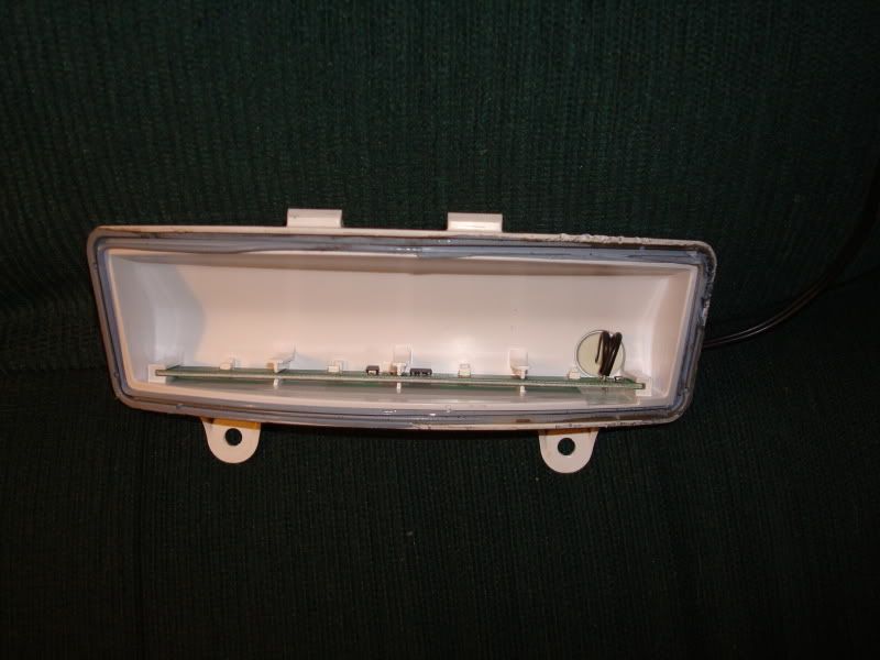
I was surprised to see the stock circuit board/LED's located in the "roof" of the housing. The circuit board is simply slid into some moled brackets, and is easily removed with a pick tool:
<A href="http://[IMG]http://i82.photobucket.com/albums/j260/harleypingman/SG%20LED%20projecgt/001-1.jpg" target=_blank>
http://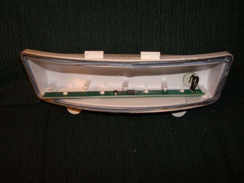
http://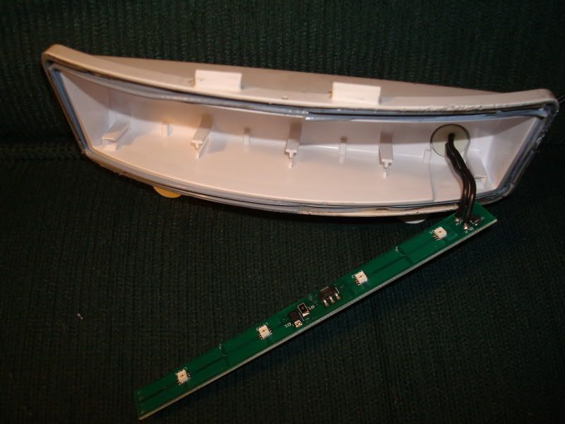
The sealant used to secure the lens to the housing is removed using the hair dryer to heat it, and a pick tool and box cutter.
Step 3--Installing the new LED's.
Here are the LED strips from Custom Dynamics:
http://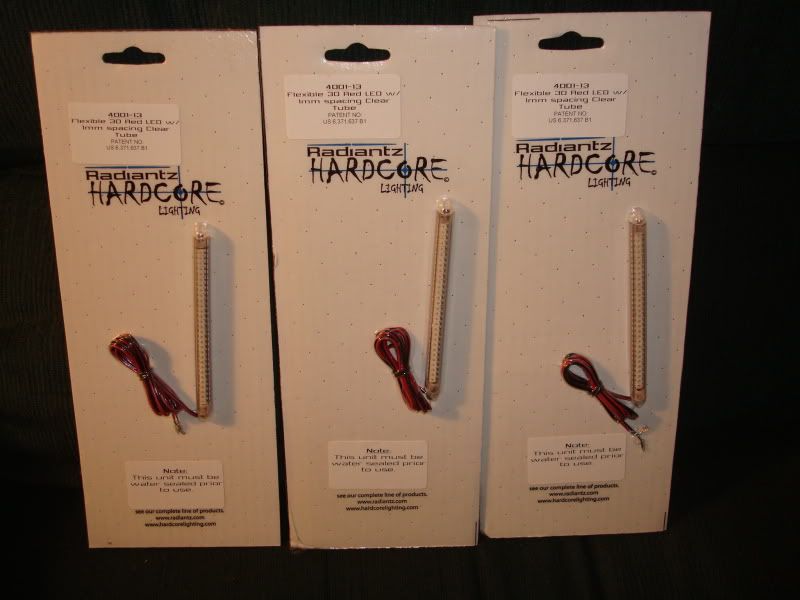
The LED strips have double-sided tape on the backs to secure them when installed.
My installation of the LED's differs from Todd's. He used clear polycarbonate cut and shaped to conform to the lens of the SG light and mounted each strip directly behind the three segments of the lens that are visible when the light is installed in the facia. He told me how to do this and I tried it but found it very slow going trying to rough cut the polycarbonate, trim the rough piece for fitting inside the lens, etc.
Since the stock LED is mounted in the "roof" of the housing, I decided to do the same. To create enough room for the three LED strips the brackets used to mount the stock circuit board are easily removed with a pair of plier to break-off the long brackets and a Dremel grinding attachment to remove the stubs. Here are the three LED strips installed in the roof of the housing:
http://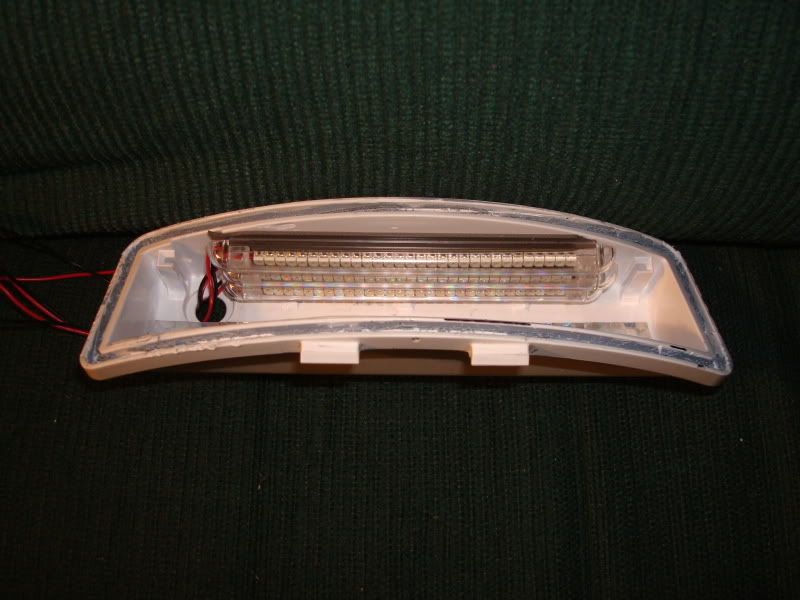
To improve the reflectivity of the white plastic housing, I lined it with some reflective tape purchased at an auto parts store:
http://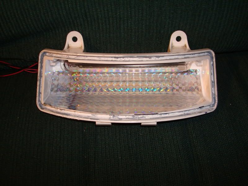
I also cut the reflective tape into thin strips and attached them to the back of the lens that is not visible when the lens is installed; the idea being to bounce the light back rather than light the rear part of the facia:
http://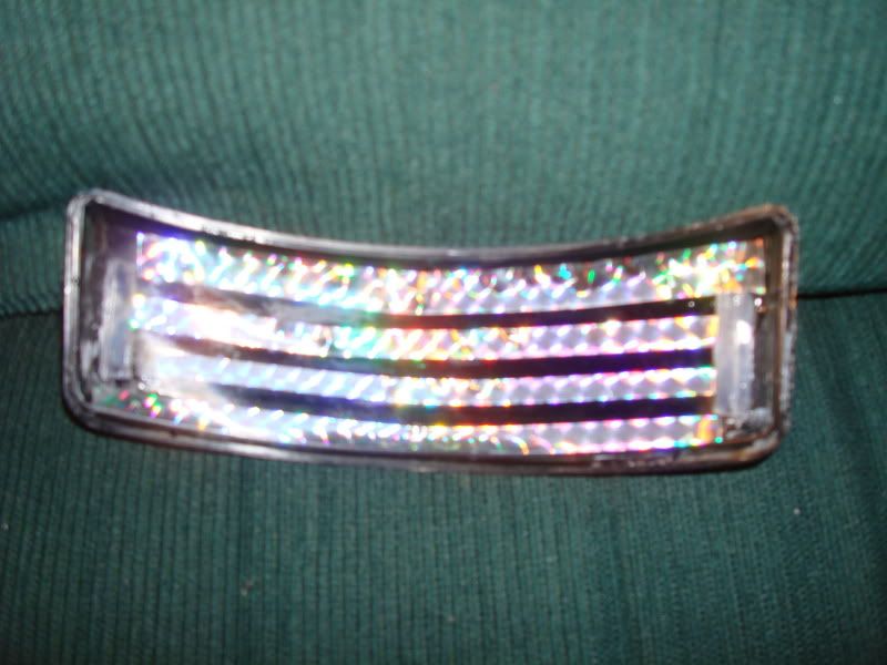
Some RTV Silicone in the hole where the wires exit the housing seals the hole, and holds the lens in the housing.
Step 4--Wiring.
Since I'm not ready to install the light in the facia (the bike's apart for a paint project), I haven't done the final wiring. However, my plan is to wire two of the LED strips as a brake light, and the third strip as the run light. Todd wired his this way with the center strip in the lens the run light, and the top and bottom strips as the brake light.
Edit: I did wire the three LED's as mentioned above: two strips for the brake light circuit and one strip for the run light circuit.
Since my strips are mounted in the roof of the housing, I doubt that it will make much difference which of the three is used for the run light. The wires from the strips will need to be shortened considerably. They will be wired along with the SG turn signal bar's license plate light and plugged into the upper left chamber of the circuit board behind the tail light lens. The connector used is a three wire connector with the far left slot the ground; center is the brake light; and, the far right slot is the run light.
Cost.
The LED's from Custom Dynamics were $26 each plus shipping. I don't have a side by side comparison to the HD run/brake light accessory, but I'm confident my project will be significantly brighter all around. I'll post some pics of the final installation and see if I can arrange some bike-to-bike pics with a buddy's SG.
Edit: Haven't arranged a side by side comparison; mine do work as brake/run lights. But with the addition of the BAL-1R tail light, I believe the BAL overpowers the LED's in the fascia.
Thanks to Todd for walking me through the modification.
Edit: Using the upper left chamber of the tail light circuit board and its three pins for ground, run, and brake light is exactly how the HD "Tri-bar Lighted Rear Fender Extension Kit," PN 91067-07, is connected, so there are no electrical issues with this set-up. Road King owners would wire their LED this way also since there is no Tour Pak harness on their bikes. Street Glides use the tour pak harness for the facia LED, but can use the tail light circuit board (by splicing in the turn signal license plate light wires) if they want the tour pak harness to use with a lighted tour pak (which is why I didn't use the tour pak harness for this project; I have an Ultra King tour pak on a detachable rack and wanted the tour pak harness for the tour pak.
Last edited by Harleypingman; 08-29-2011 at 12:07 AM. Reason: 8/28/11 edit done to add pictures and confirm functionality
#4
03-31-2009, 10:58 PM
#6
03-31-2009, 11:54 PM
This gives me an idea. Anyone ever replace the stock incandescent turn signals in front or rear w/ clear or smoke lenses? Especially the pancake style like on Road Kings, etc.?
When I did I was surprised they are just matte aluminum inside, or whatever the metal is, and not reflective in any way. I wonder if a circle of reflective metal tape in there might help w/ brightness once you switch to the colored bulbs? Seems like it would have to help. I'm gonna look into this, make sure the tape can take the heat of the incandescent and sticks to the inside surface, those would be my only two concerns.
Not to hijack, just to give you credit for the idea HPM. I wanted to subscribe to the thread anyway to make sure I see your final pics. Take care.
#7
04-01-2009, 12:13 AM
 ). Perhaps someone else will do this and report.
Trending Topics
#9
04-01-2009, 09:00 AM

#10
04-01-2009, 09:44 AM
My original post was edited to explain that using the tail light circuit board to power and control the LED strips is the same way the HD Tri-Bar Lighted Fender Extension Kit is wired for its run/brake light functions. So there is nothing new in doing so with this project.
The stock circuit board I removed works, so if someone with an SG that has a failed circuit board, shoot me a PM with your mailing address and I'll send it to you.
The stock circuit board I removed works, so if someone with an SG that has a failed circuit board, shoot me a PM with your mailing address and I'll send it to you.
Last edited by Harleypingman; 04-01-2009 at 11:05 PM.