
"DIY MODS" and TRICKS to SAVE $$$$$$


#392
 04-14-2009, 09:53 PM
I wanted integrate my garage door opener on my bike so that it was easy to use and look factory installed. I started by looking for a momentary switch that would fit in the lower dash filler. I had 2 empty slots on my 2009 StreetGlide. I went to Doc's Harley Davidson in Kirkwood Missouri and Chris knew jsut what would work, a bag lock switch part# 71764-07. I ordered 1 for myself and another for a buddy. I started by taking out the ignition switch, using a 7/8" wrench to take off the the ignition support, and then removing the position plate. Took off the 2 side screws and the filler came right off. I took it to the workshop and removed the screws for the block off plates. I then took my new switch and cut the plug off. With a DVOM I determined the red and blue wires had continuity when the lock button was pressed. I tinned the wires and then took the cover off my garage door opener. With the DVOM I again determined which points on the circuit board had continuity when the door opener button was pushed. I then soldered the wires to those points. I then cut 2 grooves for the wires. The switch was installed in the bracket and screwed back in the filler. I then used velcro to attach the door opener to the filler panel checking that there was no interferance with the forks. I then put it all back together. Took me 20 minutes and it looks factory and woorks great.
#393
04-14-2009, 10:10 PM
Did the same thing over the winter and it works great! Also added the RideTime LED rear fender kit that converts the low rear fender running light to an additional brake light. Also added the new HD AirWing Tour Pak rak with the Run/Brake light in it. Went for more lights without looking too over-the-top.
#395
04-16-2009, 09:09 AM
#396
04-19-2009, 07:24 AM

#397
04-22-2009, 02:40 PM
Cruiser
Join Date: May 2008
Location: Over the river from Cincy
Posts: 101
Likes: 0
Received 0 Likes
on
0 Posts
I just installed the Radio Shack Siren (PN# 273-079) on my 2008 Street Glide and wanted to share the installation since it seems to be different than the earlier installation post for a 2007.
The siren connector is located to the left and below the fuse block. You do not have to remove anything other than the left side cover to expose the fuse block. The factory siren connector is a 3 pin Delphi connector. It is plugged into a mock pin housing so you will need to unplug it. I put the siren red wire in the first terminal (Power) wire colored Brown/Grey and then the black wire of the siren into Terminal 2 (Signal) wire colored Light Green/Brown. I just stuck the wires into the connector, electrical taped it together, and then zip tied the siren to the left of the fuse block.
Hope this helps!
#398
04-23-2009, 01:02 AM

#399
04-23-2009, 12:45 PM
Seasoned HDF Member
I didn't want to pay for a pricey relocator when I only wanted to gain a little room. If you want a lot of room, then George Anderson's relocator is the way to go. There are two factory positions in the newer paks. I made a third. There is one little black plug in the rear middle hole that was already there. I bought a new one pn#90493-83 for the other hole as I was making a new one. To make the new holes simply take a straight edge of a piece of paper and make a mark on the paper directly in the middle of the rearmost hole and the next hole forward. Then move the paper forward so that the rear mark is now in the center of the forward hole and the forward mark is where you will mark in the tourpak to drill the new holes. This ensures proper spacing and location of the holes without having to measure. It also makes sure they are perfectly aligned with the existing holes. This was all done without having to completely remove the tourpak from the bike and cost under $3.
This picture with red circles indicates where the existing holes and hardware were located.

This picture with blue circles indicates the new holes. These are the only 3 holes that you have to drill in the pak itself. The one with the ground wire can be drilled down through while the pak is installed. The two on the sides can be drilled partially while the pak is installed on the bar, then finished while partially lifting the pak up.

This picture with orange circles indicates the new plastic plugs I used to plug two existing larger holes that were previously blocked underneath by the chrome support bar, but exposed once it was moved back.

This picture with purple circles indicates two existing holes that are used as guides to drill down through the two new holes in the chrome support bar. This ensures perfectly spaced holes in the support bar to move it back one position.

This picture shows the new position underneath in the support bar. You can see the existing hole that was there to the far right of the spacer.

This picture is a closeup of the where the bar is now, one position forward of the two existing positions.
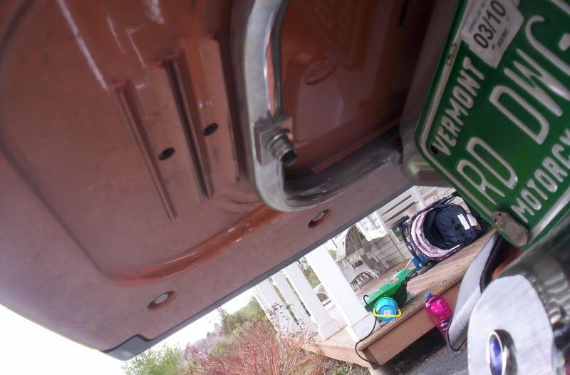
This picture is just a shot from further back showing the third position underneath.

This picture shows how much space is gained.

This picture with red circles indicates where the existing holes and hardware were located.
This picture with blue circles indicates the new holes. These are the only 3 holes that you have to drill in the pak itself. The one with the ground wire can be drilled down through while the pak is installed. The two on the sides can be drilled partially while the pak is installed on the bar, then finished while partially lifting the pak up.
This picture with orange circles indicates the new plastic plugs I used to plug two existing larger holes that were previously blocked underneath by the chrome support bar, but exposed once it was moved back.
This picture with purple circles indicates two existing holes that are used as guides to drill down through the two new holes in the chrome support bar. This ensures perfectly spaced holes in the support bar to move it back one position.
This picture shows the new position underneath in the support bar. You can see the existing hole that was there to the far right of the spacer.
This picture is a closeup of the where the bar is now, one position forward of the two existing positions.
This picture is just a shot from further back showing the third position underneath.
This picture shows how much space is gained.
#400
04-30-2009, 10:25 AM

Advanced
Join Date: Aug 2008
Location: carson city nv
Posts: 89
Likes: 0
Received 0 Likes
on
0 Posts