
Nightster Winter Makeover
#781
 06-19-2012 | 06:55 AM
Thread Starter
|
Road Master
Joined: Jul 2011
Posts: 1,167
Likes: 7
From: NY
Well, I do appreciate all the interest and good will and support from everyone following this thread. Thank you.
Here, here's the link to the site for the switches. http://www.digikey.com/product-detai...933-ND/1289397
They have a pretty large selection.
Here, here's the link to the site for the switches. http://www.digikey.com/product-detai...933-ND/1289397
They have a pretty large selection.
#782
06-24-2012 | 12:02 PM
Thread Starter
|
Road Master
Joined: Jul 2011
Posts: 1,167
Likes: 7
From: NY
11 hours in the shop yesterday, almost all of it working on the bars. They have turned into an amazingly complex project and we're still not done. It's my fault. I'm trying to make Ozzie cram 10 lbs of crap into a 5 lb bag. Here's the list of major mods to the bars:
The biggest challenge, among the 8 challenges listed above, is to do an internal throttle with bar end signals. The throttle mechanism attaches to the end of the right side of the bars and is hidden under the right grip. The throttle cable runs up through the bars and attaches in the center of the throttle mechanism, blocking any wire access to the end of the bar where the turn signal is supposed to mount. Ozzie figured out a way to get the turn signal light around the throttle mechanism without interfering with the mechanism and without binding on the grip. An ingeneous solution, he machined a small groove in the surface of the throttle mechanism just deep enough to lay the two small turn signal wires. Then he used some JB Weld to secure the wires in the groove so that the grip slides over the whole assembly and the wires remain in the groove and don't interfere with either the throttle mechanism or the twist grip. Sorry, no pics of that.
Then, he had to figure out a way to attach the turn signal on the end of the throttle assembly. Normally the bar end signals simply use an expanding flange that screws in and binds on the inside of the bars using a hollow brass bolt to allow the signal wires to pass through and securing the signal mount on the end. The signal then attaches to that mount with a couple of set screws. With the throttle assembly running right out to the end of the bars there was no place for the expanding flange and no way to attach the signal. So he tapped the end of the throttle mechanism and screwed the mount directly into it. There was just enough space to fit everything. Here's the way it looks without the grip.

The blue piece is the cap at the end of the throttle assembly. That got drilled and threaded. The black piece on the right end is the turn signal mount. That is bolted to the blue piece with a hollow brass bolt. Here's with the grip installed.

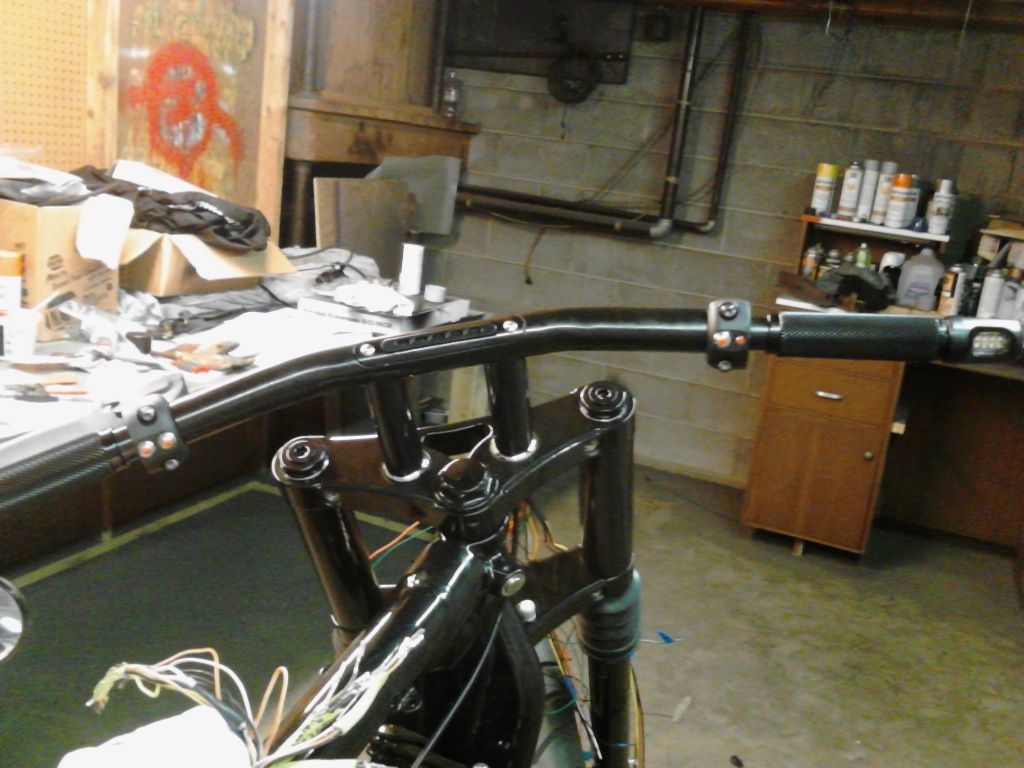
Those wire ends had to be soldered to the signal before we mounted it. Here's with everything mounted.

The left side was much easier, relatively speaking. On this side the bar end mirror complicated the turn signal mount. Here to, we ended up ditching the original turn signal expanding flange method of mounting. I machined a bung that fit inside the end of the bar and Oz welded a nut on that, then welded the whole thing to the inside of the bar end. That allowed the hollow bolt to run through both the signal mount and the mirror and bolt directly to that bung on the inside of the bars. Everything is very secure.

As you can see from the above pic, we also had to shorten the stock levers. Getting rid of the stock switch housings required shortening the distance between the grip and the switches, making the stock levers too long. So we cut those and Oz welded them back together to the right length and angle.


Oz finished them off with the hand grinder and the polishing wheel, I sand blasted them and they look amazing. Perfect length. They have some casting bubbles in the surface and I need to use some bondo to smooth them out before painting sometime next week.
Got the dummy light mount finished. That is gorgeous.

And everything is wired up, with all the wires running down the right riser and out the bottom of the top triple clamp through the 3/4" riser bolt. All those wires just barely fit. I'll probably use the same wire mesh/loom that I used on the wiring harness to run back up under the clamp to the space under the tank where everything will get soldered up and secured.

Almost finished everything last night, but after getting everything together we discovered that the throttle is now binding slightly, not releasing. At first we thought it was just a snug fit and would work itself in, but that ain't it. It was late and we just left it like that at 9:30pm last night but we'll probably have to take the throttle side apart again and figure out what the problem is. It's not the signal wires and it's not the cable. Don't really know what it is but I woke up last night at 3am and might have figured it out.
The throttle cable itself runs up and through the throttle mechanism and is held in place by a set screw. Normally, the two inches or so of the end of the cable that protrudes through the assembly after the set screw is of no concern and just dangles inside the bars, sliding back and forth with the inner assembly. But because we have the turn signal to worry about on the end that little two inch cable end had to be cut off, otherwise it would hit the signal wires every time you open up the throttle. Problem is there's very little room to use snippers to cut that cable end. There's a small 1/4" groove in the assembly right over where that cable end is, so I pulled the cable end up through that and tried to cut it as close to the throttle assembly as possible. In doing so I didn't cut all the way through the cable on the first snip and had to go back for a second bite. I'm thinking that in taking that second bite to clip the cable I may have snipped a bit of a strand I already cut, leaving a small bit of cable inside where the inner assembly needs to slide back and forth smoothly. I don't know. That might be it, or it might be something else. We'll have to wait until next weekend to find out. Cut wires. Take everything apart. ugh.
Like I said, this is/was a hugely complicated part of the project. There is a lot of cutting, machining, grinding, welding and soldering I left out of the description and didn't have time to take pictures of. The grip ends had to be machined off. The turn signal mounts had to be turned down slightly. A lot of trial and error along the way...Ozzie's trial and my error. It's been fun!
- Internal throttle
- Internal wiring
- Replace stock switches with switches in the bars
- Dummy lights in the bars
- Bar end mirror
- Bar end turn signals
- New knurled aluminum grips
- Not to mention, the new bars themselves
The biggest challenge, among the 8 challenges listed above, is to do an internal throttle with bar end signals. The throttle mechanism attaches to the end of the right side of the bars and is hidden under the right grip. The throttle cable runs up through the bars and attaches in the center of the throttle mechanism, blocking any wire access to the end of the bar where the turn signal is supposed to mount. Ozzie figured out a way to get the turn signal light around the throttle mechanism without interfering with the mechanism and without binding on the grip. An ingeneous solution, he machined a small groove in the surface of the throttle mechanism just deep enough to lay the two small turn signal wires. Then he used some JB Weld to secure the wires in the groove so that the grip slides over the whole assembly and the wires remain in the groove and don't interfere with either the throttle mechanism or the twist grip. Sorry, no pics of that.
Then, he had to figure out a way to attach the turn signal on the end of the throttle assembly. Normally the bar end signals simply use an expanding flange that screws in and binds on the inside of the bars using a hollow brass bolt to allow the signal wires to pass through and securing the signal mount on the end. The signal then attaches to that mount with a couple of set screws. With the throttle assembly running right out to the end of the bars there was no place for the expanding flange and no way to attach the signal. So he tapped the end of the throttle mechanism and screwed the mount directly into it. There was just enough space to fit everything. Here's the way it looks without the grip.
The blue piece is the cap at the end of the throttle assembly. That got drilled and threaded. The black piece on the right end is the turn signal mount. That is bolted to the blue piece with a hollow brass bolt. Here's with the grip installed.
Those wire ends had to be soldered to the signal before we mounted it. Here's with everything mounted.
The left side was much easier, relatively speaking. On this side the bar end mirror complicated the turn signal mount. Here to, we ended up ditching the original turn signal expanding flange method of mounting. I machined a bung that fit inside the end of the bar and Oz welded a nut on that, then welded the whole thing to the inside of the bar end. That allowed the hollow bolt to run through both the signal mount and the mirror and bolt directly to that bung on the inside of the bars. Everything is very secure.
As you can see from the above pic, we also had to shorten the stock levers. Getting rid of the stock switch housings required shortening the distance between the grip and the switches, making the stock levers too long. So we cut those and Oz welded them back together to the right length and angle.
Oz finished them off with the hand grinder and the polishing wheel, I sand blasted them and they look amazing. Perfect length. They have some casting bubbles in the surface and I need to use some bondo to smooth them out before painting sometime next week.
Got the dummy light mount finished. That is gorgeous.
And everything is wired up, with all the wires running down the right riser and out the bottom of the top triple clamp through the 3/4" riser bolt. All those wires just barely fit. I'll probably use the same wire mesh/loom that I used on the wiring harness to run back up under the clamp to the space under the tank where everything will get soldered up and secured.
Almost finished everything last night, but after getting everything together we discovered that the throttle is now binding slightly, not releasing. At first we thought it was just a snug fit and would work itself in, but that ain't it. It was late and we just left it like that at 9:30pm last night but we'll probably have to take the throttle side apart again and figure out what the problem is. It's not the signal wires and it's not the cable. Don't really know what it is but I woke up last night at 3am and might have figured it out.
The throttle cable itself runs up and through the throttle mechanism and is held in place by a set screw. Normally, the two inches or so of the end of the cable that protrudes through the assembly after the set screw is of no concern and just dangles inside the bars, sliding back and forth with the inner assembly. But because we have the turn signal to worry about on the end that little two inch cable end had to be cut off, otherwise it would hit the signal wires every time you open up the throttle. Problem is there's very little room to use snippers to cut that cable end. There's a small 1/4" groove in the assembly right over where that cable end is, so I pulled the cable end up through that and tried to cut it as close to the throttle assembly as possible. In doing so I didn't cut all the way through the cable on the first snip and had to go back for a second bite. I'm thinking that in taking that second bite to clip the cable I may have snipped a bit of a strand I already cut, leaving a small bit of cable inside where the inner assembly needs to slide back and forth smoothly. I don't know. That might be it, or it might be something else. We'll have to wait until next weekend to find out. Cut wires. Take everything apart. ugh.
Like I said, this is/was a hugely complicated part of the project. There is a lot of cutting, machining, grinding, welding and soldering I left out of the description and didn't have time to take pictures of. The grip ends had to be machined off. The turn signal mounts had to be turned down slightly. A lot of trial and error along the way...Ozzie's trial and my error. It's been fun!
#783
06-24-2012 | 12:10 PM
Thread Starter
|
Road Master
Joined: Jul 2011
Posts: 1,167
Likes: 7
From: NY
Oh, and I forgot to mention - one of the switches on the right side failed the first time I pushed it AFTER everything was soldered up and installed. Pushed the button in and it stuck there, refusing to return to normal position. Fortunately we have a few extras but that's another cut, replace and resolder event. Fun, fun...
#784
06-24-2012 | 12:15 PM
Tourer
Joined: May 2012
Posts: 254
Likes: 0
From: Clawson, Michigan
#785
06-24-2012 | 12:46 PM
#786
06-24-2012 | 04:09 PM
Thread Starter
|
Road Master
Joined: Jul 2011
Posts: 1,167
Likes: 7
From: NY
But, that's where this thread comes in. Love it or hate it, everyone who reads this will get an idea of just how much work has gone into this "Winter Makeover".
#787
06-24-2012 | 04:12 PM
Thread Starter
|
Road Master
Joined: Jul 2011
Posts: 1,167
Likes: 7
From: NY