In desperate need of wiring help
#11


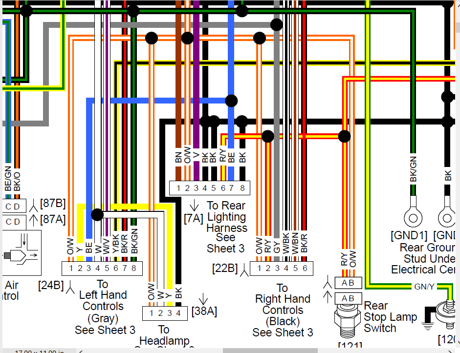
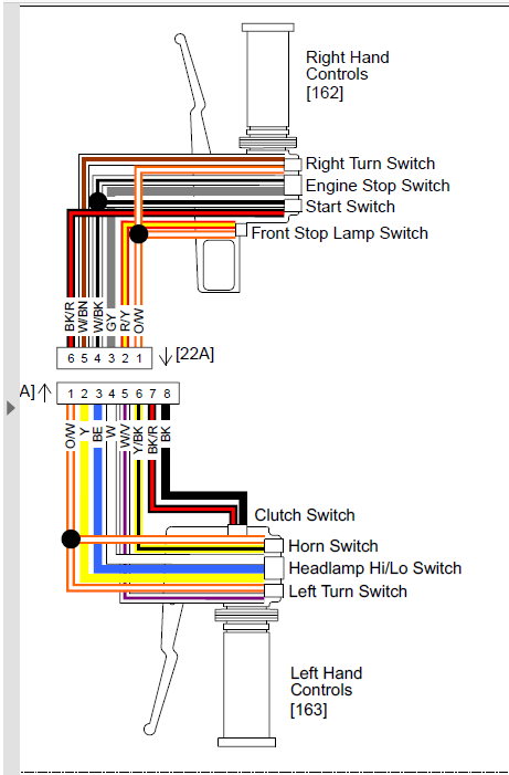
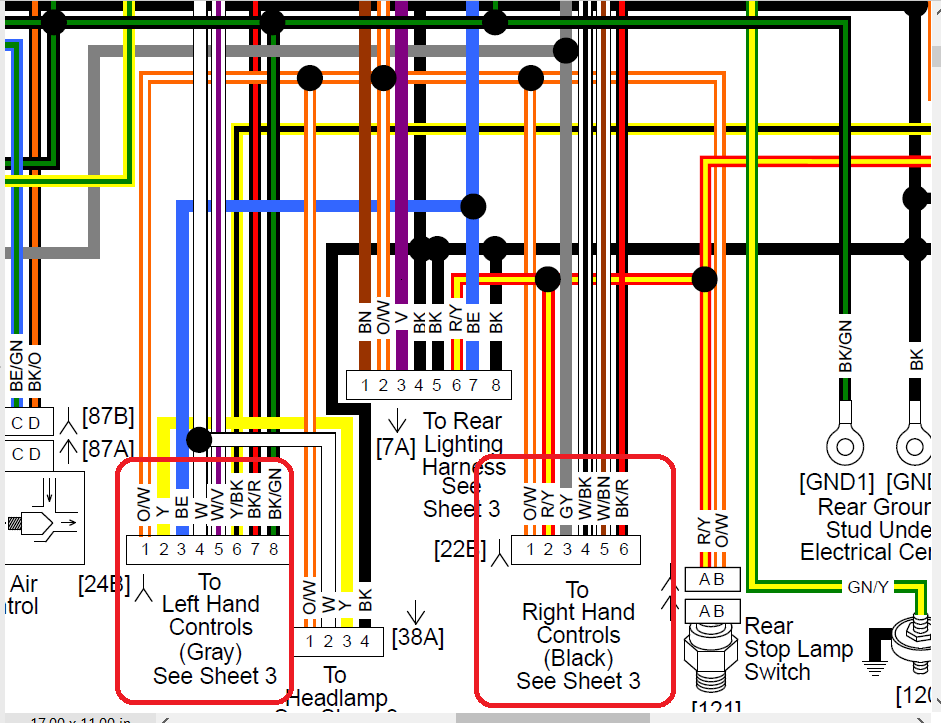
Matt, I guess what your looking for is the wire colors in the other half of the connectors that the Right & Left side hand control wiring connects to. Try this. You're looking for connectors 22A & 24A from the hand controls connecting to 22B & 24B in the main harness.
The White/Violet(Purple) is from the left side turn switch and connects to a White/Violet
The Black is from the clutch switch and connects with a Black/Green
The White/Brown is the right turn switch and connects to a White/Brown
https://www.hdforums.com/forum/dyna-...ring-help.html
You should have kept it all in your original post to make it easier to help.
Here's a great place to get wiring diagrams.
https://serviceinfo.harley-davidson....cle/lookupForm
When you get to the wiring diagrams click on the crossed arrows to expand the page and then you can zoom in on a part of the diagram to make seeing the colors easier.
Last edited by 14GuineaPig; 02-01-2017 at 05:43 PM.
#13
The left and right harness do not converge.
Each of these harnesses ends at a connector, which plugs into the main harness.
OP: can you step back from the bike a bit and snap a pic of the harness?
Without seeing the harness it is hard to tell what has been done here, I`m thinking the connectors were hacked off, and the switch harness was hard wired into the main harness without the use of connectors.
Last edited by Dan89FLSTC; 02-02-2017 at 03:58 PM.
#14
The left and right harness do not converge.
Each of these harnesses ends at a connector, which plugs into the main harness.
OP: can you step back from the bike a bit and snap a pic of the harness?
Without seeing the harness it is hard to tell what has been done here, I`m thinking the connectors were hacked off, and the switch harness was hard wired into the main harness without the use of connectors.
Each of these harnesses ends at a connector, which plugs into the main harness.
OP: can you step back from the bike a bit and snap a pic of the harness?
Without seeing the harness it is hard to tell what has been done here, I`m thinking the connectors were hacked off, and the switch harness was hard wired into the main harness without the use of connectors.
#15
#16
All three wires are from the right side harness. All other from right side wires are connected to corresponding colored wires.
The three wires in the pic have no wires to connect too. The two switches in the pic is also from the right side. One half is the start/kill and the other have is signal.
I posted the pic to show that all wires are connected and have no others to connect too.
I can take a further back pic tonight when I get home of this disaster I'm dealing with.
#18
I was talking about the picture in the original post. If those wires are from the right side harness you do have issues as there is no black or W/V wires from that side. You might have to find where they land at on the other end of the harness. I'm also curious where you landed the W/Bn from the right side if you haven't connected the W/Bn wire at the harness.
Last edited by Jay Guild; 02-03-2017 at 12:51 PM.
#19
Matt
About your pictures:
Pic #1 - Is that the main harness that you are holding? Did your turn signals work before you started this bar change?
Pic #2 - Looks correct - Stop/Run - White/Black Stripe & Gray
Start - White/Black Stripe & Black/Red Stripe
Note: The 2 White/Black Stripe wires join to each other and continue as 1 White/Black Stripe wire to connector 22A position 4
Pic #3 - Looks correct - Brake - Orange/White Stripe & Red/Yellow Stripe
Right Turn - Orange/White Stripe & White/Brown Stripe
Note: The 2 Orange/White Stripe wires join to each other and continue as 1 Orange/White Stripe wire to connector 22A position 1
So coming from the right hand controls you should have 6 wires going in to a 6 pin connector in the following order
#1 - Orange/White
#2 - Red/Yellow
#3 - Gray
#4 - White/Black
#5 - White/Brown
#6 - Black/Red
These wires in connector #22A should plug into connector #22B on the Main harness which has the same color wires in the same positions.
Edit: The only place that I see W/BN or W/V used is in the main harness from connectors 22B & 24B to the TSM/TSSM or in the hand controls from connectors 22A * 24A to the turn signal switches. I checked all the 2008 Dyna wiring diagrams.
Last edited by 14GuineaPig; 02-03-2017 at 01:57 PM.


