The rebuild is going pretty well, for anyone following. But I do have some questions about wiring, and about the original "layout" of the 68 FLH handlebar controls. Any help here would be immensely appreciated.
1A. On the original 68 FLH, the wiring diagram shows the left handlebar with the headlamp switch and the right handlebar with the directional signal switch. Easy enough. But I have two-position and three-position switches, and I wanna make sure I have what I need where I need it before I button everything up on the front end. Anyone have any insight here? I assume the left side headlamp is two-position (hi/low) and the right side is three-position (left blink/off/right blink). The service manual and parts catalog don't make it very clear.
1B. The new aftermarket switches I got are prewired yellow/black/red. They do not correspond with the original diagram, which lists green/brown/red for the right side directional switch and three reds with white/black/yellow tracers on the left side headlamp switch. I'm not super skilled at wiring outside of following the harness diagram, so if anyone can help on this one I'd appreciate it.
2. On the diagram, the Generator Armature shows a single green wire to the Generator Signal Light before turning into a dashed line (BLACK) that connects to a junction terminal (7) then on to the oil signal light (50). The dashed lines are just meant to indicate that if the circuits aren't functioning correctly (i.e. dysfunctional generator or no pressure at the oil pressure switch) then they'd trigger those lights to activate, right?
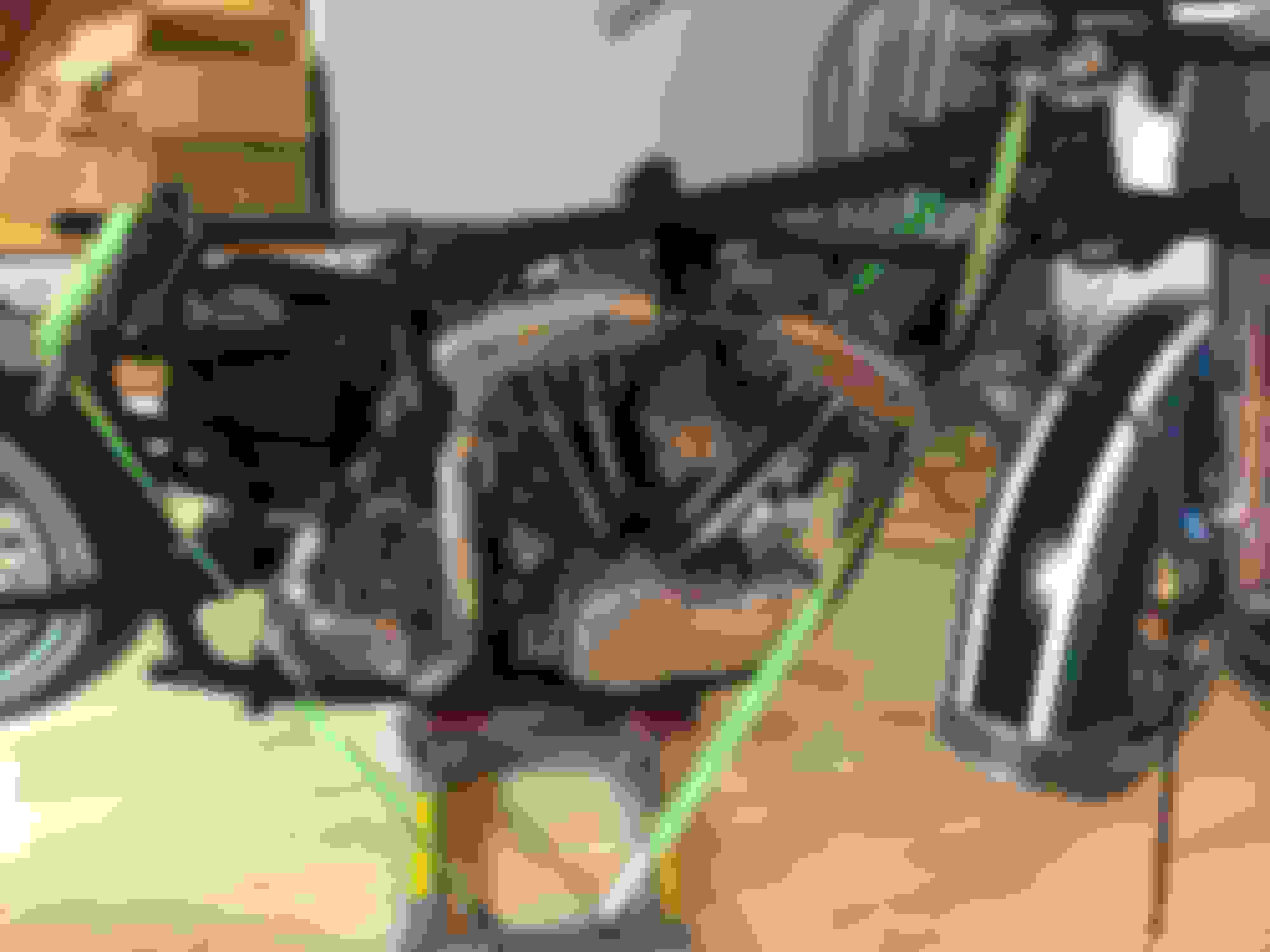
Here's where the project stands (literally) in my living room at the moment. Hopefully only about a month away from firing her up for the first time in 30+ years.
The Headlight has a 2 position switch - it goes from low beam to hi beam and is only powered when the ignition switch is turned to light - you already know that i am just explaining it this way for clarity
the directional switch - the center position has no power to the other two wires - its back and forth so what you deside what works for you in left or right - push one side pull it back for the other and the dash lights must be tied to the thing as well left and right
In my shop we sometimes do things other dont agree with - like we leave off the right side gas tank off when the bike is first finished - this allows we too ride and tune the adjustable main on the bendix and at a stop the not only the mix screw but the idle speed - quickly with ease
and i ride it 20 minuets 3 times just to be sure before installing the other fuel tank - because my big hands get burned and scratched the other way - this works for me
1A. On the original 68 FLH, the wiring diagram shows the left handlebar with the headlamp switch and the right handlebar with the directional signal switch. Easy enough. But I have two-position and three-position switches, and I wanna make sure I have what I need where I need it before I button everything up on the front end. Anyone have any insight here? I assume the left side headlamp is two-position (hi/low) and the right side is three-position (left blink/off/right blink). The service manual and parts catalog don't make it very clear.
Yes 2-position switch for your high/low and 3-position for your directional signals
1B. The new aftermarket switches I got are prewired yellow/black/red. They do not correspond with the original diagram, which lists green/brown/red for the right side directional switch and three reds with white/black/yellow tracers on the left side headlamp switch. I'm not super skilled at wiring outside of following the harness diagram, so if anyone can help on this one I'd appreciate it.
Use a volt/ohm meter (doesn't matter which of the two wires you are testing goes to +/-) to determine wire is active/hot; only two will be active when you change the switch position (not sure if I am making this clear or not)
2. On the diagram, the Generator Armature shows a single green wire to the Generator Signal Light before turning into a dashed line (BLACK) that connects to a junction terminal (7) then on to the oil signal light (50). The dashed lines are just meant to indicate that if the circuits aren't functioning correctly (i.e. dysfunctional generator or no pressure at the oil pressure switch) then they'd trigger those lights to activate, right?
Correct
Nice project you have going there
And as John suggested I also just mount the left tank for trials. Helps for fine tuning and to get a better look at the motor and such re: leaks and the like.
Thanks everyone! I haven't posted a video in a while but if anyone wants to see a snapshot of how the last year has been going, my rebuild playlist is at
. Unfortunately for those who *are* interested, I'm having more fun building than I am recording my progress...so...sorry 'bout that.
But shouts to the forum. Usually I can find the answers I need already in the archives, so I only post questions that I can't find solid answers to elsewhere. Don't wanna offend anyone here by being lazy.
Sorry for the huge thumbnail, didn't intend to promote anything here, just share the journey. I've learned a ton in the past year.
I had the switches reversed, and I was just planning on leaving them and wiring accordingly...but in trying to stick to the original (and coupled with my inexperience in wiring) I moved them to their rightful spots. Now I won't have to fudge around and I can stick right to the SM diagram.
 04-14-2021 | 05:20 PM