Fuse / circuit Breaker location on 1983 Sportster XLX-1000
I have a 1983 Sportster XLX-1000 that I'm finally gonna have up and running again. But I have som electrical problems. the previous owner swapped all wires so the color coding of the wires are all some what messed up.
Does anyone know the order/layout for the fuses / circuit breakers that are located under the seat on the rear fender? They are lined up two and two. Which one is the ACC, IGN , Main and Lights
See drawing of the fuses.
I can't help with the exact layout, but according to the wiring diagram for an '83 XLX, two of the circuit breakers have their copper input posts shorted together with a (copper?) bar. Those two are the ignition and accessory breakers. The ignition breaker has a wire attached to the input (copper) post along with the copper bar, the accessory breaker should have only the copper bar from the ignition breaker attached to its copper input post (no wire).
The main circuit breaker will have a large-ish wire going directly to the + terminal of the battery from its copper input post.
This is my 1978. They are horizontal. Top right is the MAIN, reversed so all those wires fit better [extra circuits for extra parts], the single wire on the left goes to the battery. Under it is the LIGHTS with blue wire. Top left is ACC [every orange wire on the motorcycle originates here], bottom left is IGN. "I think" I have this described correctly
Here is where I added in an extra circuit breaker for the extra electrical circuits...
I am creating the diagram in visio, checking the ground against the service manual. Hopefully tomorrow I will have verified the layout and will share it with you guys
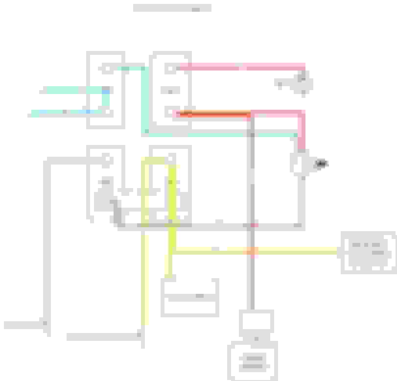
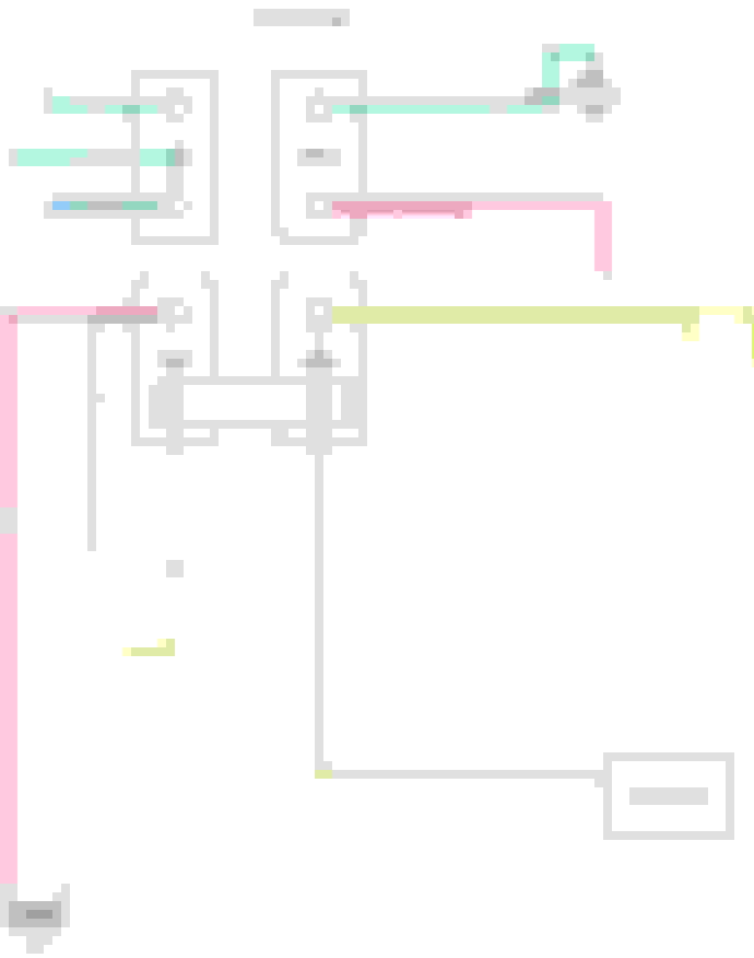
So I did the job of investigating and compare to the service manual. And here are the simplified wiring on my bike and the wiring from the service manual. The diffences I can see is that my bike has a green wire from mail to the battery where it should be red and the the IGN breaker is directly connected to the coil and not going via the stop switch. So basically, once the Ignition switch is on, the coil is weaponized.
Well it has actually been a stroll down memory lane, I haven't used the bike for 10-15 years and prior to that I haven't done any work on the bike for several years before that due to moving and lack of garage space. So first I discovered that the Mikuni carborator I once had on the bike was replaced after a crash my brother done and repairs via insurance. The mechanic shop replace my Mikuni with a old Keihin carburetor without telling me. And since I was living in another part of the country I wasn't able to inspect the repair. Well the shop is bankrupt many years ago so I can't go and make my complains. https://www.hdforums.com/forum/carbu...tify-carb.html
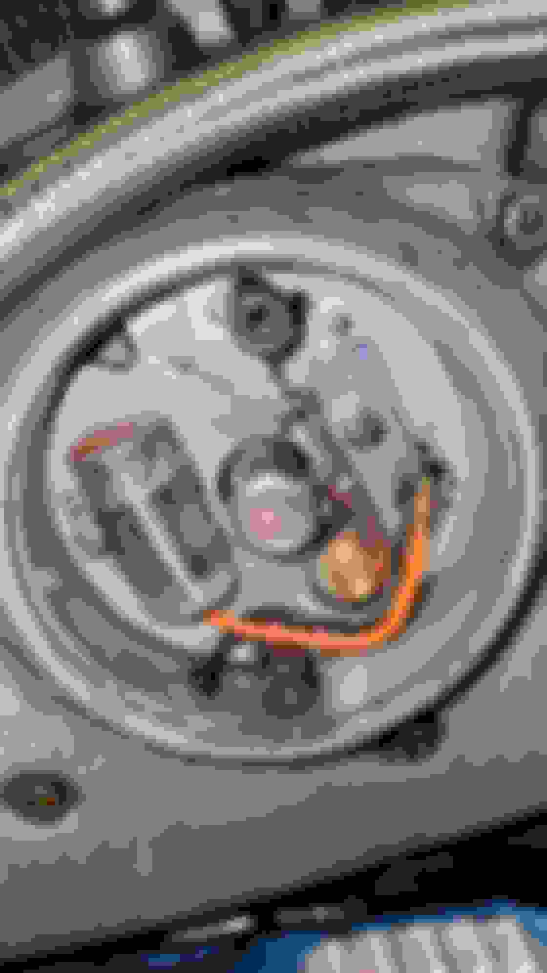
Now I'm looking into the electrical installation and discovers that the electronic iginition is swapped with Point Breakers. That is actually something I might even remember doing my selves. I had a lot of issues with the electrical system and swapped to Point Breakers at some time. Forgot all about it but some investigation of whey the Electronic module isn't connected and then inspecting the truth behind the Points Cover. So now I'll guess my next task is to adjust the point breakers.
This is so much fun walking down memory lane and getting my bike back in order. Cant wait for the first ride :-)
 03-25-2021, 04:34 PM