Why is there wet oil on the top of my pistons?
Is what I’m wondering.
I rebuilt the top end of this 95 evo (45k mi) a few months ago. It had no oomph going up hills so I did something about it. I found that the PO had put new pistons in and not cleaned up the cylinder walls. So they were in need, shall we say.
I had the cylinders machined +010 over, replaced the cam bearing, put an ev13 in, new kb pistons (had the Indy who sold them to me put the rings in those) and the used the stock pushrods and also reused the lifters after carefully checking them out. I used James gaskets.
I rode it about 30 miles and was concerned about a clatter that occurred above idle speeds as well as being annoyed by what I assumed was valve train ticking. I don’t mind a little tappet noise but couldn’t shake the feeling something was amiss.
anyway I decided that reusing those stock lifters was perhaps not the wisest decision, especially with a somewhat more aggressive cam so I popped off the rocker boxes in order to install new ones and then kept going to have a look inside the cylinders.
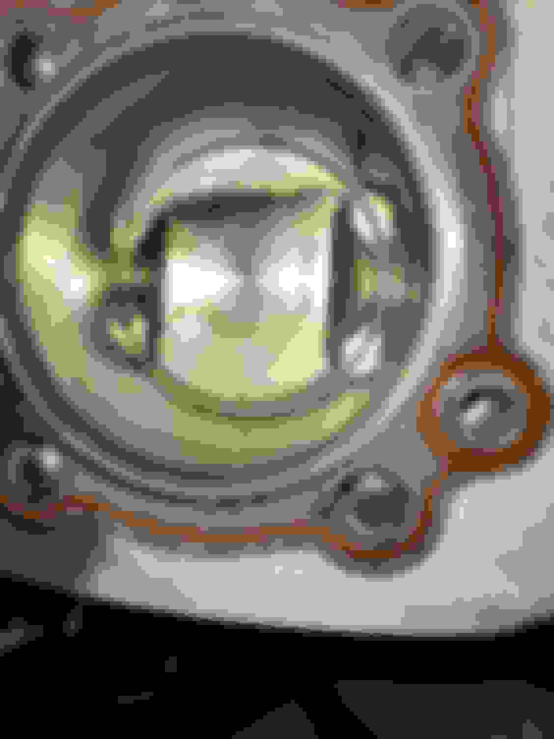
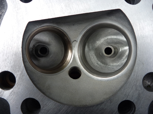
they look like this: Rear Front
So for all you experts - why is wet oil on this side of the pistons?
I’ll have another look but I didn’t see any oil residue on the carb or intake manifold.
Wipe down the cylinder walls and get a better photo of the cross hacking on it. If not cross hatched, then rings will not mate in correctly, and could be the problem with why the oil rings are not mating in, scrapping off the oil correctly on the down stroke from the walls, since crank itself slings the oil up under the piston to lube the walls and wrist pin and it bushing that way.
As for oil channel back down, gasket looks fine.does not use the added O rings, does not look to be leaking around it, so only other leak would be down from valve guide leaking at the valve steam.
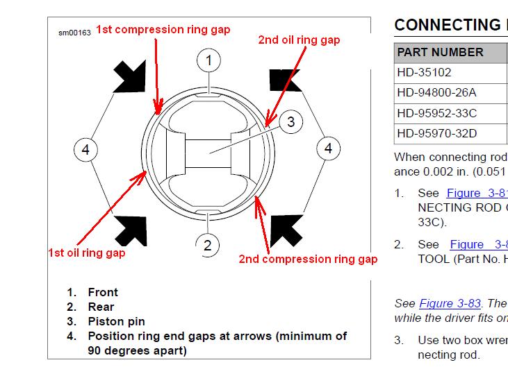
P.s, with the head pulled, will need to replace the base gasket as well, so may as well pull the jugs to check the gaps on the ring set, to make sure they are spaced correctly as well.
Hence look the below photo and note how the rings should have been gaped.
Also to note, rings are going to take a little longer than 45mile to mate in, so a little oil leak past the oill rings is normal for this low of mileage on new rings.
So would expect some oil still on the walls, but this appears to be more than just oil ring break in by pass, and would suspect maybe leaking valve seals as well.
Next, and on this set of pistons, arrows should be pointing on the intake manifold for both jugs. hence on oem pistons, you point the arrows at the front of the motor, but on this set of pistons, arrows for the front piston, should be pointing at the back jug, and on the back jug, arrows should be pointing at the front jug. The reason for this, the bottom of the piston spacing for the connection rods is off set, and if arrows are in the wrong direction, then off set for the connection rod will cause connecting rod binding.
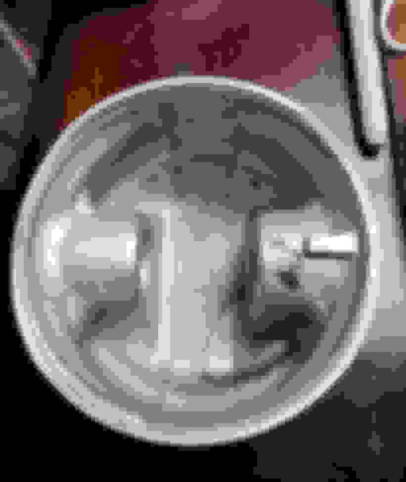
Hence here you can see the off set on the bottom of the oem piston, and the side with the raised tab on it, always goes toward the primary side of the motor/sprocket side of the motor.
Yours are a little different, with the pistons marked front and back, and on both of these piston, the arrow is telling you to point it at the intake valve for each cylinder isntead, so arrows point to the each other cylinder, isntead of both to them to front of the motor like on stock pistons.
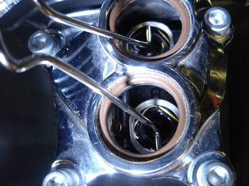
Lastly, double check the wear on the top connecting rod bushing for the wrist pin,since if you can rock the wrist pin in the bushing side to side up and down more than a hair, the noise man not be coming from the lifters, but the wrist pins to bushings instead.
As for new lifters, depending on the lifter and if adjustable push rods in play, figure out the total amount of piston travel in the lifter, and adjust the push rods for half that distance. If using the solid push rods, make sure to get them in the correct placements,and should have at least .040" pre load on the lifter. Hence when you set the rocker boxes for each cyclinder, cam lobs for that side need to be downward so your not preloading the rocker, and when you set the rocker boxes before tighten the bolt, push rods should have the head the .040' gaped from begin seated, and then your going to use the 4 large rocker channel bolts cross patterned to draw the rocker box down to pre-load the rockers with the top of gasket on the head, bring those to torque, then go after the smaller bolts cross patterned to tighten and torque them to spec. Once once rocker box is down, the rotate motor to get the cam lobs on the other jug side down, then same as the other side, to make sure that you have about the .040" gap between rocker box to top of head.with gasket in the middle) before you go after the 4 large bolts cross pattened tightened to draw the rocker box down even as well. I bring this up,since may end up with a lifter that may not give the correct pre load with stock solid push rods.
Also, if lifters are problem, then check cam lobes to make sure that the cam lobs surface hardening is not work down, and change the cam inner needle bearing out as well every time you change the lifters (koyo B138,and lettering.numbers on the one side of the bearing always go outward, not towards the crank, since the lettering side is the stonger side, that will go against the press tool to drive it in to the channel).
As for direction of lifters in blocks, look at the side of the lifter to see the oil channel, and that oil channel always is aimed to the jug side of the motor. Hence on evo lifter blocks, oil comes in to the inner channel from the jug side, oil flows around it to the middle of the two, and then through a center channel to flow to the outer channel, so always want the side point in the direction of how the oil is coming into both channel. Also, make sure to use the alignment bolt bolts to install the lifter block, so you don't end up with the motor to inner block oil passage miss alignment.
Note, make sure clean motor side and bottom of blocks well, and do not use any gasket sealer on the block gaskets.
Just need two, to go cross side to hold the block is alignment to oil passages, tighen the real two bolts to torque, pull the aligment bolts to add the other two real bolt to toque them in place last.
As for holding the lifters in the block as you install the block, since the lifter have to be bottom loaded, large paper clip spring piece works well to hold them in place.
To add on the "no oomph part" (an no mention of if different cam in play as well), pistons look to be higher compression pistons, so did you increase the fuel to the motor with compression and displacement increase, with the bike not now running too lean now instead?
Also, some more radial cams come on later, so if say running a ev27, and lose of some lower end power, could explain that part too?
Wrong head gasket? bore size looks incorrect, also look where the rings stop at the top of the bore, you sure those are not stroker pistons? Unless they're hypereutectic and the rings are further down on the pistons.
You should of had almost too high compression with domes and an EV13
yes no, maybe on the wrong size head gasket, hence not out of line to use the standard head gaskets, verses a .010 over bore gasket, with a .010 over bore.
Hence even with pop up pistons, side areas of piston top of still the same as standard pistons, since Piston outside at top of stroke should still have at least .020" squish, and not be touching the ring of gasket in the first place.
Hence evo heads, and if top sides of piston do come up to be level, or above the top of cylinder wall (no squish gap), then piston would be slamming into bottom of head at some point with enough connecting rod wrist pin bushing wear.
But back to the question is squish was checked,since base of jugs could have been faced to much, decreases the squish distance with stock piston, and the pop ups top sides may be coming up even farther.
To messure squish, bring pistons all the way up with jugs bolted down and base gasket in play, run a straight edge on the top of jug,and use feeler gauges to to messure down to the top of piston sides. Stock should be around .030", while 020" in not out of the question with some pop ups that are pushing compression isntead.
If your into the .010", then try to get it back to .020" with thicker base gasket. The reason for this, the connector top rod bushing loves to wear on the faster side, and with slop there, on the dead stoke and standard head gasket in play with with the .005" of ring over lap, just too easy to have the piston slamming up into the gasket sealing ring.
As for single piece head gasket, verse MLS, would be going MLS .010" with the raised compression on the motor, due to the pop ups.
While this seems to be getting off topic.. I would not runs a 0.020" squish. 0.030 would be the tight side for me.. Tighter than that and you can get contact. As far as being worried about 0.010 over hitting the sealing ring, I wouldn't.. Most are 0.040" to 0.050" larger than the std bore. Still good to check tho.. The big issue on early TCs was that the headgasket needs changing when going to 95 ci.. Also going to 98, requires a head gasket change as the 95s hang a little over the cylinder edge.
 01-31-2024, 08:41 PM