Super Cool Guy Here
#41
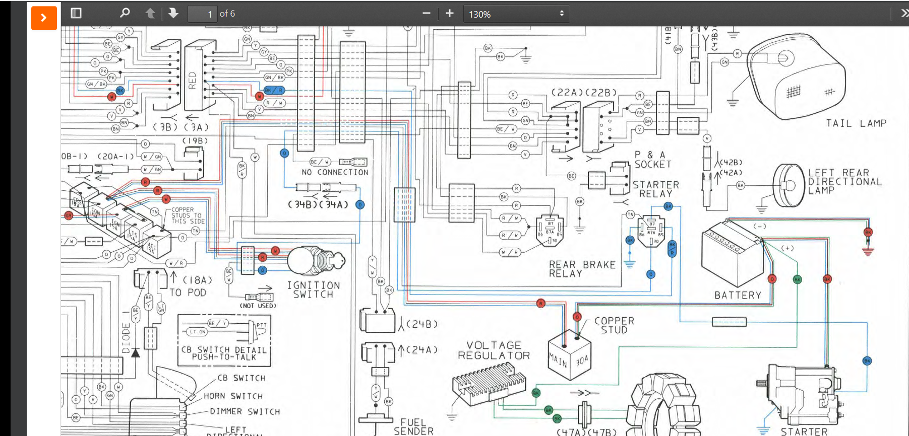
Connecting the VR at the silver stud protects the wiring going back to the VR, in case it shorts to ground. I think this is the reason for connecting at the silver stud.
Most vehicles have no breaker between the alternator/voltage regulator and the battery. Harley connected the VR at the copper stud for many years.
Most vehicles have no breaker between the alternator/voltage regulator and the battery. Harley connected the VR at the copper stud for many years.
so what do you think... I have an acc wire (red) a voltage regulator wire black with a blue band on it... and a wire that is connected to the same post as my postive cable on the solenoid or starter motor... which ones should be paired in your opinion on which posts?
Last edited by 0003; 03-31-2021 at 10:58 AM.
#42
Have you looked at the wiring diagram in the link that I posted?
It shows the wire from voltage regulator connected directly at the positive battery post.

Last edited by Dan89FLSTC; 03-31-2021 at 11:44 AM.
#43
Is that a 93 wiring diagram for this model?
#45
#46
Where do you get these diagrams? I looked up an actual 93 service manual but couldnt find a physical copy.
Im really curious why when comparing the start and stop relay the ground is reversed from 86 yo 85... all relays are the same so why aren't all sockets wired the same... more curiosity than function need
Im really curious why when comparing the start and stop relay the ground is reversed from 86 yo 85... all relays are the same so why aren't all sockets wired the same... more curiosity than function need
#47
#48
The factory used to connect the voltage regulator wire to the copper stud on the main breaker, up to early `90s or so, then they switched over to the silver stud.
The layout of the clymer diagrams are not great, a lot of them are incorrect.
Here is the real deal:
Harley Davidson Service Information Portal
The layout of the clymer diagrams are not great, a lot of them are incorrect.
Here is the real deal:
Harley Davidson Service Information Portal
I feel like somehow I'm missing links and attachments when I read your posts initially. Maybe its when I read them from the email notifications.
I've asked a couple times earlier but maybe the posts were too busy to pick out the question.
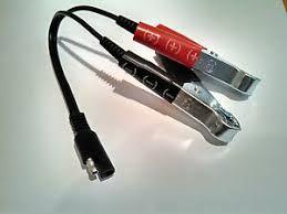
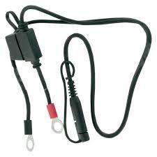
What might have happened when I plugged this

Which was Attached to my battery... into this...

Also attached to my battery...
It popped and smoked...
My surprise and recoil ripped the alligator clips right off..
What did I potentially do?
I just want to make sure I didnt cause another major problem that couldn't have been caused another way and therefore be very difficult to find.
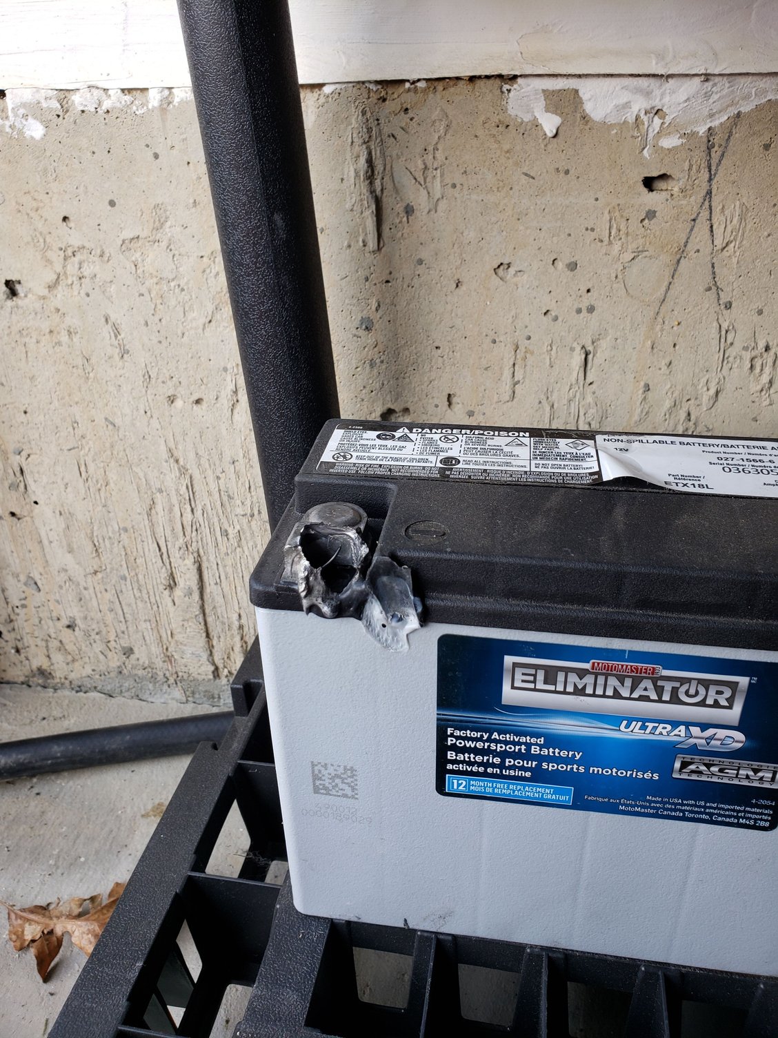
Remember... next time I started bike.... this happened...

Thats on the negative side.
#49
#50
The battery post melted because of a poor connection, most likely it was loose.
If you connected both of those units via the sae plug, then you crossed your battery connections (shorting the positive directly to the negative), it would have just blown the little fuse.
If you connected both of those units via the sae plug, then you crossed your battery connections (shorting the positive directly to the negative), it would have just blown the little fuse.
I'm trying to print that wiring diagram.... I want to print it huge at staples. Id like to color it and draw arrows representing current flow. Current flow arrows would make these so much easier to understand.


