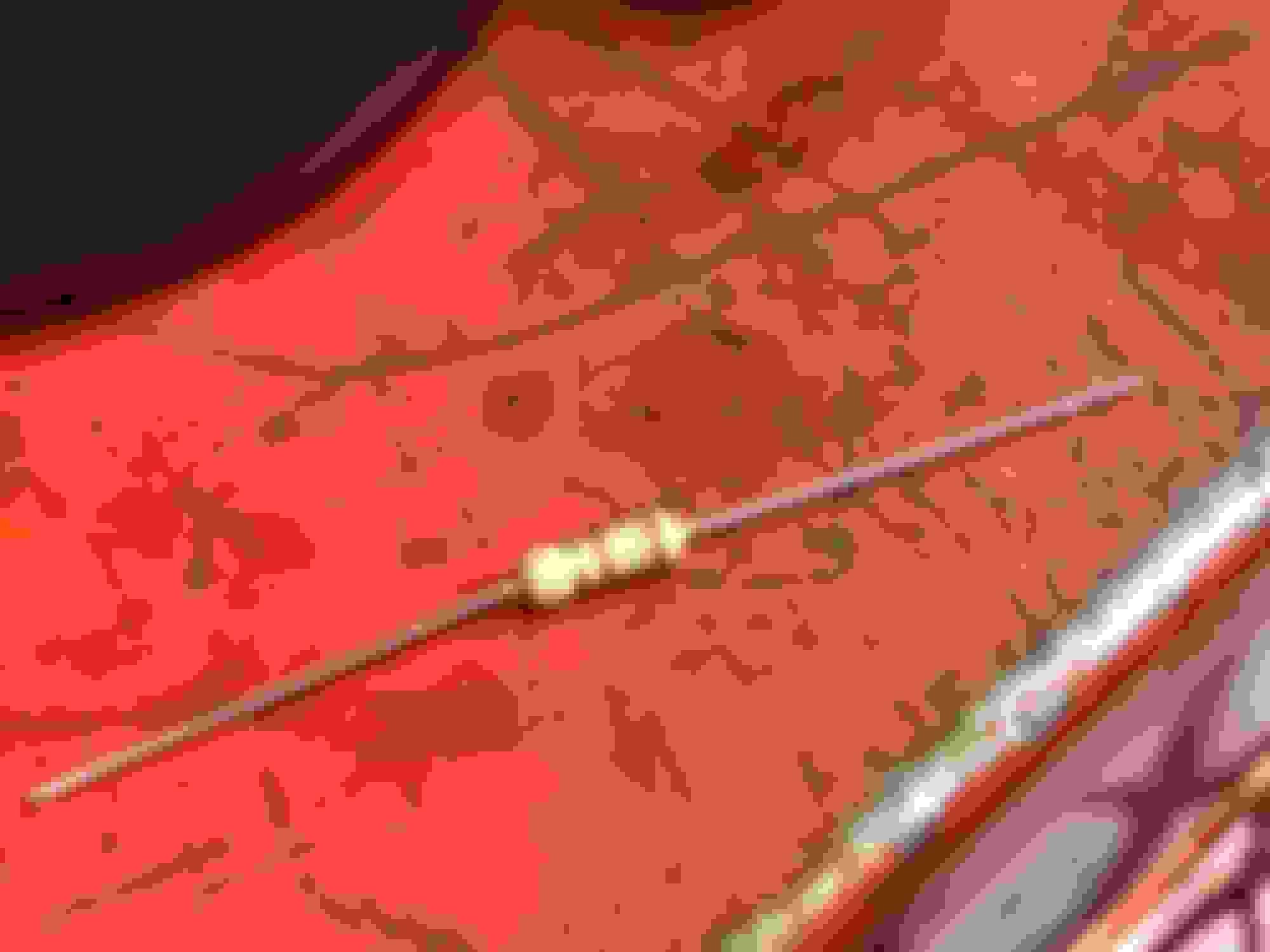
I've slowly been adding and upgrading lighting on my 2014 FLD and today I had an interesting problem. For 2014 bikes the BCM can learn the resistance of LED bulbs and you won't have a hyper flash problem. I installed all the LED's and the lights flashed normal but the dash indicators hyper flashed. I checked the codes and it had 4 codes for all 4 lights, so I let the hazards flash about 16 times and I still had the same problem, but I rechecked the codes and only the codes for the front lights came back. The front lights I used were a different style so for the hell of it I checked the resistance and found the front bulbs had a higher value then the rear. What I ended up doing was digging through my wiring drawer, grabbed a couple of 175-OHM resisters and soldering them parallel to the front signal bulbs. I did the hazard relearn procedure and all is well!
Here is a side by side comparison of the original 1157 incandescent bulb and the new LED.
Nice work! The last photo doesn�t show up. I am curious to see the comparison shot.
unfortunately the last image was hosted on photobucket and we all know the tragic ending to that story, but tomorrow during lunch I'll dig through my photo's and see if I can find the original.
Nice work! The last photo doesn�t show up. I am curious to see the comparison shot.
here is the side by side video.
<iframe width="560" height="315" src="https://www.youtube.com/embed/NtFBpvWl9RY" frameborder="0" allow="autoplay; encrypted-media" allowfullscreen></iframe>
From the description and pix it looks like what you did was put two 190 ohm (from the color bands, they look like 190 not 175) resistors in series and then put that pair in parallel with the light.
If that's the case, then you have: P=((14.3*14.3)/380)/2=.27 watts. Assumptions: system voltage = 14.3 with alternator running, turn signal duty cycle = 50%.
Those look like 1/4 watt resistors. Running them at full rated power in an enclosed space and wrapped with heat shrink tubing means they are likely to fail at some point, maybe next summer. Not a catastrophe, of course, but if the signals start to blink rapidly again, that could be the problem.
It's a 180 ohm resister per the color bands in parallel with the lighting circuit, I think at the time I just checked it on my meter and it came out to 175. They do get warm but not overly hot and worked fine for 7,000 miles before I traded the bike in. I was in a jam and that is what I came up with.
 10-22-2016, 08:31 PM