Rear Turn Signal Disassembly
#11
 02-02-2011, 03:58 PM

Road Captain
#12
02-02-2011, 07:51 PM

It is EXACTLY what I need as I want to lower my fronts to the forks and remove the mini-sissy bar (useless) from the rear of my FXDWG. Looking the manual makes my blood run cold. Hell just to change the fronts sigs they say you gotta pull the wires all the way out.
How do they connect to inside the signals?
USMAMule
How do they connect to inside the signals?
USMAMule
#13
02-03-2011, 01:58 PM

Join Date: Feb 2007
Location: Harmelen (The Netherlands, Europe)
Posts: 9,002
Received 876 Likes
on
584 Posts
Here are some images:
Tools I used to open the turn signal housing:
- coin to take off the lens
- my home made extraction tool
- 4 mm blade flat blade screw driver to feed the grommet into the housing

Step 1:
Take off the lens using a coin wrapped in a piece of paper tissue
Step 2:
Use the extraction tool to pull out the socket assembly

Step 3:
Take the screw driver to push the vulcanised grommet into the housing and feed the wires:

Step 4:
Pull out the socket assembly :


Step 5:
Use the screw driver to push in the (driving light) connector's retainer tab and pull out the connector (don't forget to lift up the tab when re-installing the connector into the assembly):

Step 6:
Feed the wires and pull out the turn signal contact seating:

Step 7:
Slide back the turn signal contact seating and notice how the contacts are crimped onto the wires:

When I mounted the aux lights to my Dyna

I had to feed and route the turn signal wiring inside the aux lights. I cut off the metal contacts, routed the wiring and re-soldered them onto the wires.....
Tools I used to open the turn signal housing:
- coin to take off the lens
- my home made extraction tool
- 4 mm blade flat blade screw driver to feed the grommet into the housing
Step 1:
Take off the lens using a coin wrapped in a piece of paper tissue
Step 2:
Use the extraction tool to pull out the socket assembly
Step 3:
Take the screw driver to push the vulcanised grommet into the housing and feed the wires:
Step 4:
Pull out the socket assembly :
Step 5:
Use the screw driver to push in the (driving light) connector's retainer tab and pull out the connector (don't forget to lift up the tab when re-installing the connector into the assembly):
Step 6:
Feed the wires and pull out the turn signal contact seating:
Step 7:
Slide back the turn signal contact seating and notice how the contacts are crimped onto the wires:
When I mounted the aux lights to my Dyna
I had to feed and route the turn signal wiring inside the aux lights. I cut off the metal contacts, routed the wiring and re-soldered them onto the wires.....
The following 3 users liked this post by FXD2003Rider:
#14
02-03-2011, 02:49 PM

I am not 100% following. To pull wires through fender you have to take them out of the AMP connector. To do this the back side pops up then I stuck a jeweled screw driver in and the wires popped out. Since I relocated my signals I did not need to reuse bolts I just cut them with a cut off saw as it was quicker and easier. Plus I can say I took a hack saw to my bike before I rode it. 
#15
02-03-2011, 07:05 PM
THANKS FXD2003RIDER.
That should help me out a great deal. I noticed you had the whole wire out - I assume you disconnected at the AMP connector end under the seat and pulled the wire out through bundled harness. Was that a rough process? If you ran into trouble how did you over come it?
I think ya'll can tell I am super nervous about screwing up what is essentially a new bike. My baby only has 7K on the odometer! LOL
USMAMule
#16
02-04-2011, 12:34 PM
Join Date: Feb 2007
Location: Harmelen (The Netherlands, Europe)
Posts: 9,002
Received 876 Likes
on
584 Posts
The images in my previous post show the front turn signal.
On my Dyna (2003) the rear turn signal wires run from the turn signal housing through a hole in the fender strut & fender along the inside of the rear fender towards the tail light where the amps connect into the circuit board as shown in the image taken from mud's post in this thread:
https://www.hdforums.com/forum/dyna-g...connector.html

Take a look at these videos by mud on how to take out the wires from the AMP connector:
http://www.youtube.com/watch?v=RNc0M74G4_Q
http://www.youtube.com/watch?v=myPysAK2bWA
On my Dyna (2003) the rear turn signal wires run from the turn signal housing through a hole in the fender strut & fender along the inside of the rear fender towards the tail light where the amps connect into the circuit board as shown in the image taken from mud's post in this thread:
https://www.hdforums.com/forum/dyna-g...connector.html
Take a look at these videos by mud on how to take out the wires from the AMP connector:
http://www.youtube.com/watch?v=RNc0M74G4_Q
http://www.youtube.com/watch?v=myPysAK2bWA
The following users liked this post:
ABQ-Jammer (05-21-2019)
#17
02-04-2011, 06:20 PM
Road Captain
#18
02-06-2011, 11:58 PM
#19
02-07-2011, 02:26 PM
Join Date: Feb 2007
Location: Harmelen (The Netherlands, Europe)
Posts: 9,002
Received 876 Likes
on
584 Posts
No need to after you've read this contribution by Citoriplus:
Here's a cheap way to help get good solder connections when you need to lengthen, shorten, or add lines in the bikes electrical system.
The biggest problem with soldering wires on a bike is you need to be an octopus. You need a couple of extra hands to hold the wires whileyou use solder with one hand and the iron in the other. So I came up with a simple and cheap way to make a couple of different wire holders.
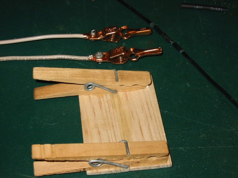
I think I spent a grand total of less than a buck for both of them, and that's because I wanted to get a new pair of alligator clips. The wood one was made from a pair of cloths pins glued to a couple of pieces of a paint mixing stick I got from Home Depot for free. The clips I swiped off the wife. This one is good for any wires that you can lay on a table, or you can glue a magnet to the back and stick it to any steel surface.
The other one with the alligator clips I mademade from the clips and a one foot long piece of scrap 12ga solid copper wire. Its great for using where you can use a clamp or vise grips on the wire between the clips and bend the ends to wherever you need them. Just be careful of using metal clips like these. A hot iron on the wores will have the teeth melting through the wire insulation. So you might considerfiling the teeth down a little and covering them with some tape or shrink tubing.
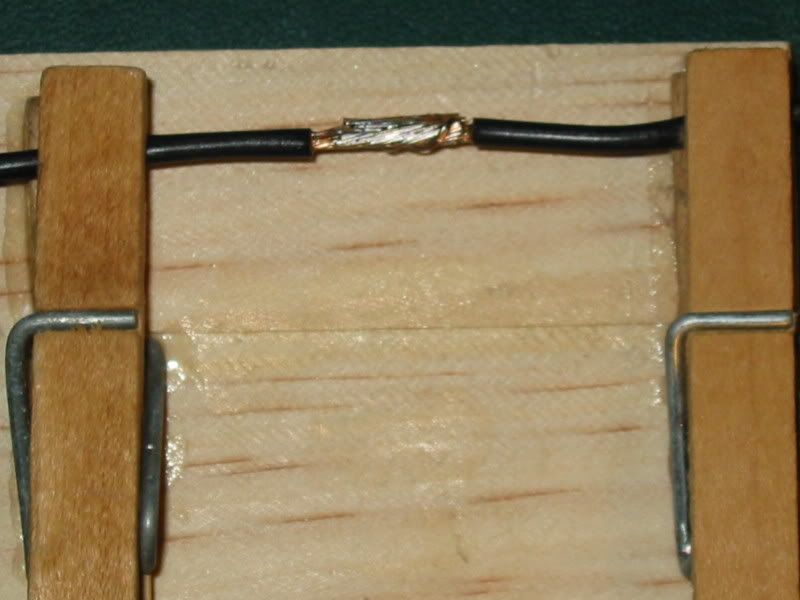
Soldering wires isn't rocket science, but it does take a little practice to do well all the time. But here's a tip for making solder connections that are nearly bullet proof. Once you get the wires soldered properly, like this.
Get some of the wives nail polish or some of this liguid tape and paint the exposed wire and solder connection.
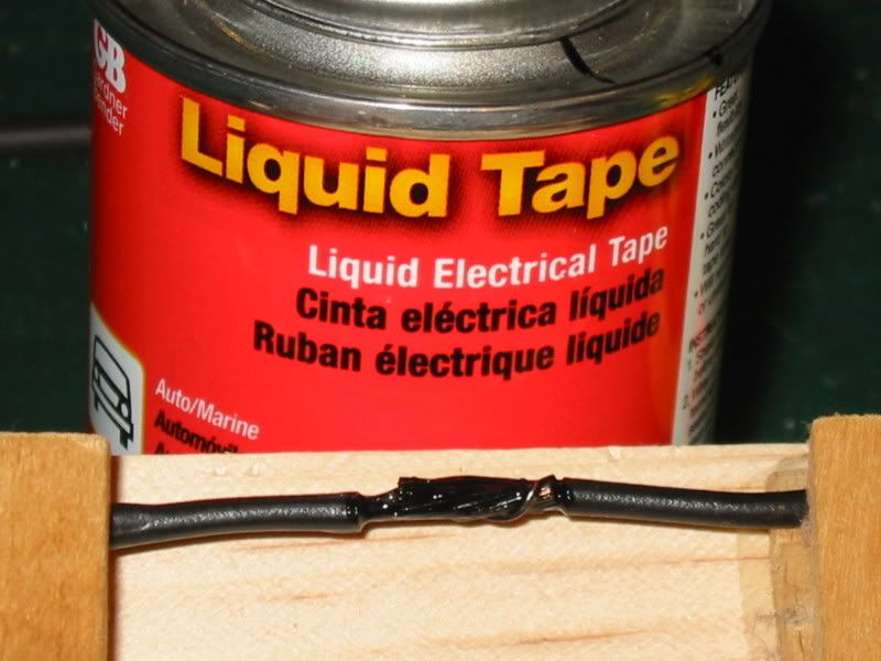
When you ‘paint’ the connection pay particular attention to the ends of the insulation and make sure its well coated. This will prevent any moisture from migrating up the wire strands and corroding them. It won't bother anything today, but a couple of years down the road it will drive you nuts trying to find the electrical gremlins.
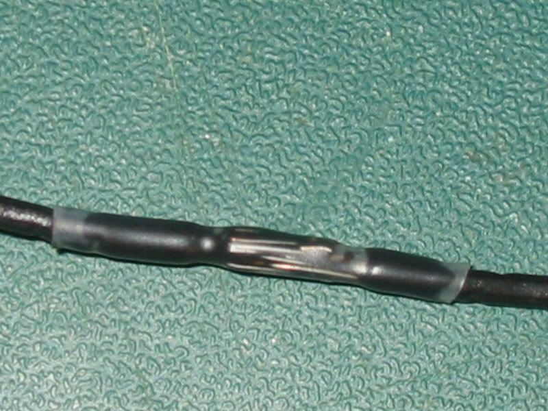
Once its dry use a good grade of heat shrink tubing to seal and protect the connection.
Done right the connection will be only slightly larger than the original wire size and last a lifetime.
This is what it looks like before I heated the shrink tubing.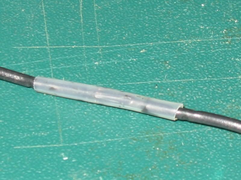
And after.
And here's one where I spliced one wire to an existing line.
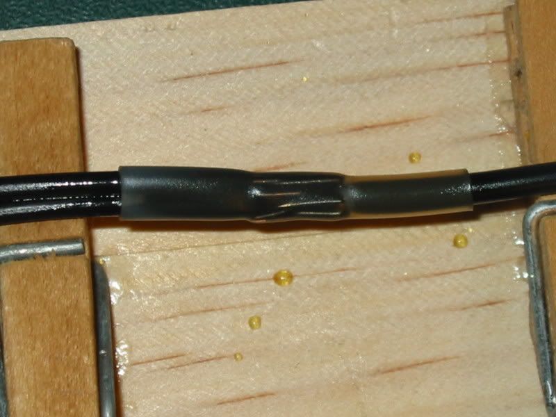
Ride safe.
The biggest problem with soldering wires on a bike is you need to be an octopus. You need a couple of extra hands to hold the wires whileyou use solder with one hand and the iron in the other. So I came up with a simple and cheap way to make a couple of different wire holders.
I think I spent a grand total of less than a buck for both of them, and that's because I wanted to get a new pair of alligator clips. The wood one was made from a pair of cloths pins glued to a couple of pieces of a paint mixing stick I got from Home Depot for free. The clips I swiped off the wife. This one is good for any wires that you can lay on a table, or you can glue a magnet to the back and stick it to any steel surface.
The other one with the alligator clips I mademade from the clips and a one foot long piece of scrap 12ga solid copper wire. Its great for using where you can use a clamp or vise grips on the wire between the clips and bend the ends to wherever you need them. Just be careful of using metal clips like these. A hot iron on the wores will have the teeth melting through the wire insulation. So you might considerfiling the teeth down a little and covering them with some tape or shrink tubing.
Soldering wires isn't rocket science, but it does take a little practice to do well all the time. But here's a tip for making solder connections that are nearly bullet proof. Once you get the wires soldered properly, like this.
Get some of the wives nail polish or some of this liguid tape and paint the exposed wire and solder connection.
When you ‘paint’ the connection pay particular attention to the ends of the insulation and make sure its well coated. This will prevent any moisture from migrating up the wire strands and corroding them. It won't bother anything today, but a couple of years down the road it will drive you nuts trying to find the electrical gremlins.
Once its dry use a good grade of heat shrink tubing to seal and protect the connection.
Done right the connection will be only slightly larger than the original wire size and last a lifetime.
This is what it looks like before I heated the shrink tubing.
And after.
And here's one where I spliced one wire to an existing line.
Ride safe.
The following users liked this post:
DG422 (05-20-2019)