Dyna Glide ModelsSuper Glide, Super Glide Sport, Super Glide Custom, Dyna Glide Convertible, Super Glide T-Sport, Dyna Glide Police, Dyna Switchback, Low Rider, Street Bob, Fat Bob and Wide Glide.
. Molex connector poking tool. The 06 handlebar controls used Deutsch.
In 07 they went to Molex.
.
.
Very simple to remove the wires. (pix follow)
First off you have a hook tool........
.
Insert the hook tool into one of the D shaped holes
and the point will aim at the other Dhole.
. .
Above, use the tool to pull up about a quarter inch.
(you are pulling up the secondary lock)
.
Now, below I show a little T wrench I made up,
(for the primary lock)
using.032 stainless steel wire.......
. .
Now, below, this is where you wanna poke your tool.
Doesn't take much, you don't need to bend anything.
Just push your tool in gently,
and pull it out the back (the wire).
. .
.
All of the high performance fittings that are used these days are marked.
Whether they be AMP, Deutsch, or Molex (pictured below).
..........they are all marked...........................................
.
.
.
. .
.
Gonna move the Deutsch and Amp technique to next in line here.
I posted these here before, but it's all spread out.
. .
mud............
.
Last edited by mud; 03-01-2015 at 10:17 AM.
Reason: reload missing pictures
.
I've received several emails over the last two years asking about
extracting wires from the ever so popular AMP connectors.
HD uses these in several locations on their machines.
Here's the last one:
mud,
I picked up the short standoffs at the dealer today and wanted to
install them tonight but am unsure about the process.
Someone on the forum said you cut the wire for each signal and splice into it,
but the directions don't say anything to that effect.
They mention something about undoing the plug from the rear tail light area instead.
I've never done any electrical work on my bike before
so I'm not really sure if these mod is out of my league.
Any chance you might be able to decipher the instructions
and give me some tips on doing the install?
Thanks,
******, yeah nice to hear from you.
I am a strong believer in NOT cutting wires.
Yes, remove the lens, then unplug the fitting.
Really very simple to disassemble the electrical connectors
so you can pull the wires thru the standoffs.
I've heard quite a few folks on the forums
brag on how fast they can cut the wire and then solder.
Sadly, that bit of misinformation is a joke.
I can extract several before you can even get out
the snips, soldering gun, solder, shrink wrap, heat gun, etc.
Patience is a virtue while mastering this technique on the first wire.
After that, they get easier.
I can release them in a matter of seconds now.
Same is true for the other connectors that HD uses -
Deutsch, Packard, Delphi -
NO need to BUY SPECIAL extraction tools for any of these.
Here ya go:
Remove the two screws that hold the taillight to it's housing.
Use a small screwdriver to push the lock tab down a little,
and pull the fitting out.
.
.
.
.
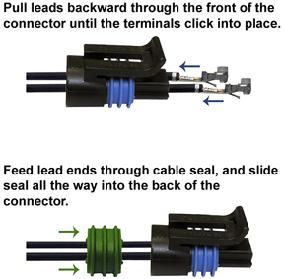
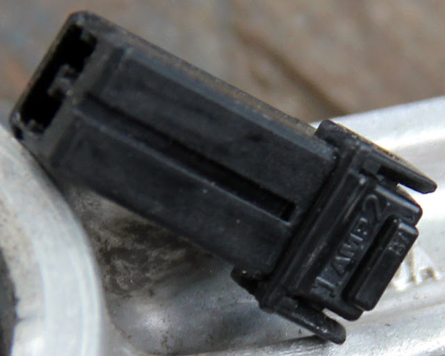
This image below shows the 2 hole AMP and the tip of the 16 gauge wire I use.
Blue arrow shows a slight bend, and the tip is hammered flat.
Red is the first lock to undo. This is what holds the wires in the fitting.
Green is the tab that you released in the first step above,
it locks the fitting to it's receiver.
Green on the right is opened way up for some of the pix farther down.
Don't bend it out or you will ruin the fitting.
They are cheap, fifty cents or so.
.
.
.
.
Blue below, better shot of the 16 ga tip.
.
.
.
.
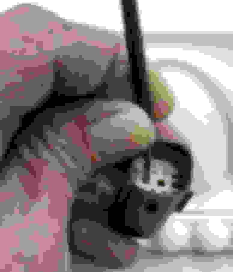
Next image you see I put an S bend in my release tool so I can control it better.
Also here you see that I have the turn indicator wire pushed fully IN
while raising the lock tang inside.
.
.
.
.
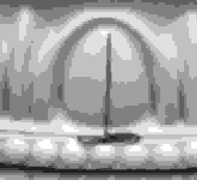
Now, below, once you have the lock tang lifted,
extract the wire.
.
.
.
.
Don't forget to pay attention to which wire comes from which side of the fitting.
There are small numbers on the housing.
In this case. 1 is purple, 2 is black.
.
.
.
.
Next two images illustrate where the tang is, and where the tip of my tool needs to be.
Green is pulled way up here simply for the photo.
.
.
.
.
I suggest buying a couple of new sockets so you can fold this way wide open
for your first try at this. If need be.
Little blue arrow indicates how far the end of the tang lifting wire needs to be.
.
.
.
.
I made two video tutorials.............................
These are great fittings, but, they are not watertight.
Green below shows a generous dab of dielectric compound on the tip of a little brush.
Red - the fitting is full
.
. .
.
.
.
.
.
Above - HD rear standoffs.
Below - close standoff on left. Stock on right.
.
.
.
.
.
Last edited by mud; 05-08-2011 at 07:59 AM.
Reason: add videos
Mud - just a reminder for your wire crimper you made. Thanks - watie.
.
Here ya go watie -
.
. ****Deutsch fitting crimper****
.
I made this up a couple weeks ago when I replaced bars,
and needed to crimp about a dozen of the little Deutsch bastards.
mud..........
.
.
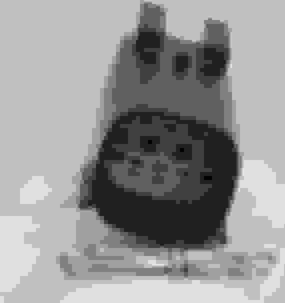
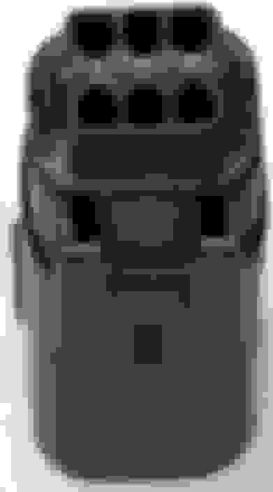
Illustrated below is a six hole Deutsch.
There is one of these for each of the left and the right hand controls.
They are great fittings, positive connection,
and, just like fish pus sy, totally watertight.
Easy to open up, pry gently with a small flat bladed screwdriver
in one of the little slots in the edge of the locking wedge.
.
.
.
.
Once you have it opened up,
the red arrows indicate the springed locks.
The green arrow is pointing to one of the locks
that I have relaxed by pushing it sidewaze with the small flat bladed screwdriver.
Then simply pull the wire out through the backside.
The orange wedge shown above locates the fittings precisely for engagement,
and prevents the locks from disengaging.
.
. .
.
Pictured below are the individual components -
Housing w/attached seal, wedge, and backend seal.
.
. .
.
The wires penetrate the rearend seal
The red arrow shows one of my crimps with my modified flea market dykes.
.
. .
.
Below is shown a rack of female Deutsch wire ends,
and my crimper.
Used a tiny needle file, and, a small square file on each jaw.
.
. .
.
Dykes work real good for this purpose,
cause each jaw tapers from thick to sharp at the cutting edge.
So, when filed inward, the crimping surface widens out just right.
.
. .
.
As shown below, file in one thirty second deep,
and one eighth wide, on each jaw.
.
DR asked about wiring taillite, so, I am updating this one with more info.
ORIGINAL: d r
Mud:
I've got an 07 Street Bob. I'm doing away with the factory tailight so
I won't have the luxury of using the connector plugs that are in the factory tail light.
So I was wondering how anyone else that has done this did the wiring?
In other words what color wires went where?
I have the service manual and have that same diagram.
I guess I'm just wondering if you can run the wires directly to each other?
For instance, can I run the violet and brown wires to the directionals
with a ground and they will work properly?
Thanks,
ORIGINAL: mudpuddle
d, yeah the colors are all there for you in your service manual,
and yes you can run them directly.
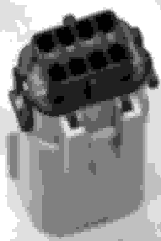
The circuit board distributes the 6 in to 8 out.
If you can tuck that HD cicuit board somewhere out of the way,
it will save a lot of misery cause you can use the high quality
HD AMP connectors that you have on hand.
When I built the tail/turn/license assembly for my 06 mudSickle,
I did not have room for the HD circuit board so I used a 6 hole
watertight Delphi connector.
First picture below is an example of the Delphi sealed connector - a 2 holer.
Second pic is the light that I built for the mudSickle -
fire in the hole - turning right.
man I love this thread. working on lifting the front and lowering the back of the tank on my Sprint Bob project (see custom forum) and was going to weld on new higher bung's for the front but was having a hard time finding the right size for an acceptable price. (almost $30 through Custom Chrome) then I remembered seeing some tank lift posts here.
Dawg Rider to the rescue. https://www.hdforums.com/forum/3260093-post824.html
I already had the parts and paint so total cost is about 1 beer. when I get the shortened rear mounts welded on i'll post a pic.
thanx Dawg
Drag pipes suck...ya ya I know. Especially 2" drags. S&S specifically calls them out as "never recommended" But that is what I have, and wanted to tune the carb and help smooth out the flat torque spots... so this was the first step.
I added the brass wing-nut as it fits the rest of the bike. Total cost $4.23. The baffles are tunable, simply adjust the angle of the 1/4x20 thumb screw and go for a ride.
Last edited by soldierbot; 04-02-2021 at 07:46 AM.
Sorry for the dead string Mud, I'm new at this (and been in Atlanta for a week which is why I haven't responded until now).
Recycle
There is an alternative. Looks the same as the stock seat, because it IS the stock seat, but there's no comparison in the ride. And, the cost is well..... uh... negligible...
DIY - Saving the seat, ditch the "seat compartment"
I finally DID SOMETHING to change my sore rear end situation that I haven't seen addressed on any of the related posts.
I performed a seat compartment-ectomy on my seat last night. I simply removed the "seat compartment" (2" of HARD plastic that takes the place of what is usually FOAM) that HD installed in the seat to accommodate that "half seat" my wife complains about when we take a ride. It bought me 2" of soft comfort and put me "into the bike" more. You can't even tell the change has been made by looking at the bike but you sure can feel the difference! No comparison.
All it cost me was the price of an electric stapler (to plant the staples deep enough into the hard plastic seat bottom) and a piece of foam (and I did drink a couple of icy beverages during the operation).
It was simple, just remove the seat, remove the staples, pop the 4 rivets (they're easier to remove from the top side with some wire cutters) that secure the seat compartment to the hard plastic seat bottom, cut & shape a piece of 2", medium density foam, with a couple of strips to build up the back raised area (you'll see what I mean) and put it back together. 1.5 hours max and that's only because I was treading on new territory (a couple of pics below)
The Rock pictures are after I added the V&H Big Radius (a bit cliche I know but I still believe they are right for this bike), Power Commander and Stage 1 (the chrome flame handles and foot pegs were already done when I bought it from a local dude). I'll take some more later but there really is no way to tell I've changed the seat without either flipping it up or sitting on it.
The other shots are the top and bottom of the seat compartment that I removed during the operation. I hope you'll be able to see the four holes that once contained the rivets that secured it to the seat bottom. That's really all that held it together.
Here's a freebie. I was tracing some wiring on the wiring schematic in the factory manual. What a pain as all those black lines are easy to get mixed up with each other. So I scanned the wiring diagram and opened it in Microsoft Paint. I traced the wiring with colored lines that come as close as I can to the color of the wire.
Before:
After:
Last edited by mud; 01-01-2009 at 10:29 AM.
Reason: resize the oversized picture
It's been mostly well below freezing....snowing....raining....and/or windy as heck and it really didn't take that long. I've got it printed out and inside a document protector inside the service manual.... It's all for the bike and maintenance....just making it easy on myself. Feel free to use it if you can...but this particular one is for a 1986 - 1990 FXR. If you scan a copy of your particular bike's wiring schematic and e-mail it to me, I'll colorize it also. Don't give me a time limit, and I'll get it back to you as soon as I can.
Dave
Originally Posted by SC-Longhair
All I can say is Thanks. That must have taken some time to do.
Last edited by chengdave2003; 12-31-2008 at 04:24 PM.
 12-24-2008, 10:46 AM


 .
.