Early TC Issues?
#31
 05-20-2016 | 11:44 AM

Tourer
Joined: Jan 2016
Posts: 312
Likes: 6
From: charleston wv
Love this thread I have the a 99 lowrider and was thinking about doing this exact thing if you don't mind me asking how much is the complete set up cams,gears,gaskets, bearings. And also how hard is it to open up the rockers and get them back together right I've never been in the motor before I have seen some videos of the cam part but everybody in the videos either leaves that part out or goes with adjustable pushrods
Also do you have a press or if not how are you installing bearings and cams
Also do you have a press or if not how are you installing bearings and cams
#32
05-20-2016 | 12:48 PM

Thread Starter
|
Tourer
Joined: Feb 2016
Posts: 309
Likes: 39
From: Southlake Texas
OK...back from lunch. Here is the breakdown of parts and tools:
S&S 510G gear cam kit...This is locked down by S&S, kinda like Apple does, where it's the same price everywhere...at $729. I did manage to find a slightly better deal on EBay, and the seller messed up the shipping, so I actually got it for $612.
Gasket set...HD 17045-99, only without the bearings that come in the OEM kit. JP Cycles for $55.
Needle bearing removal/install tool Ebay $88.
Dial indicator and base. I had these, but you can find them for roughly $50.
Then of course, you need typical tools, like sockets, torque wrenches and the like.
I do have a harbor freight press that I bought 25 years ago for $99. I see it's the same price even today! You can do the job without the press. It is easier if you have one, but I would not go buy one just for the cam job.
So, back to work...!
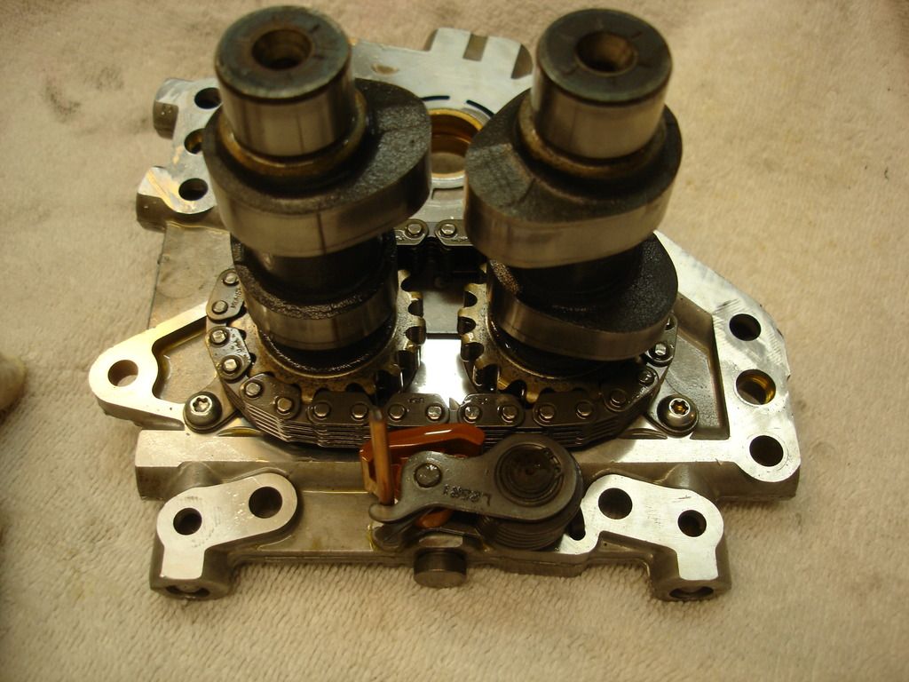
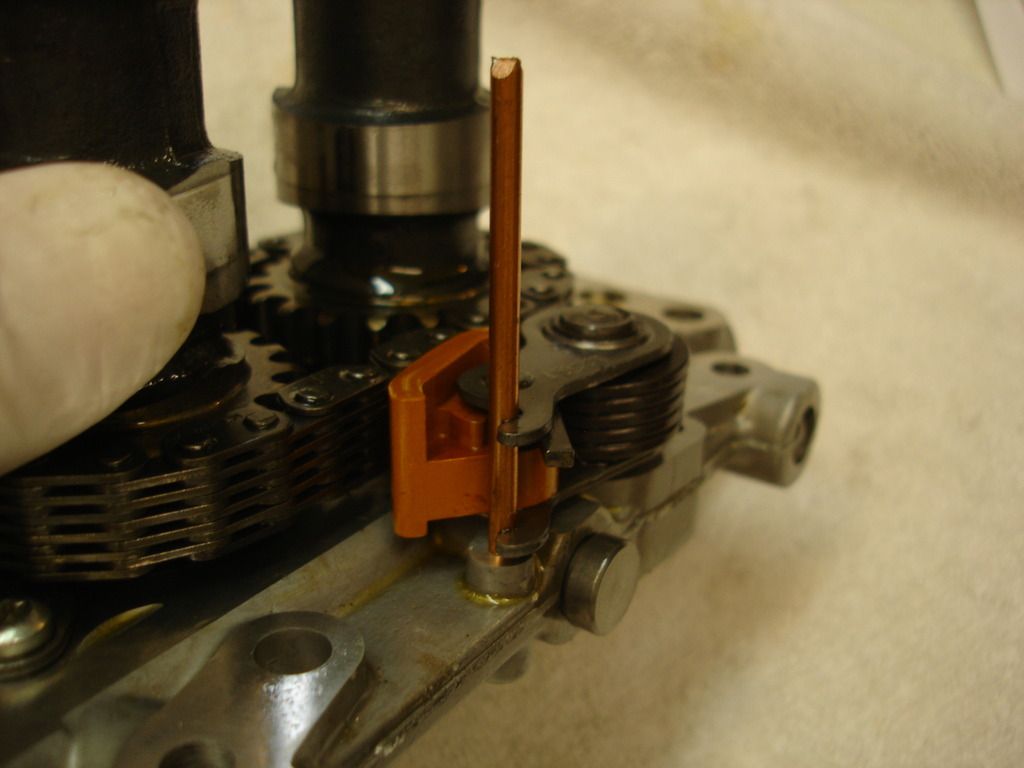
This is how the cam plate comes out following disassembly. Notice I was too cheap to buy the tensioner tools, so I used a short length of 1/8" welding rod to hold the tensioners back.
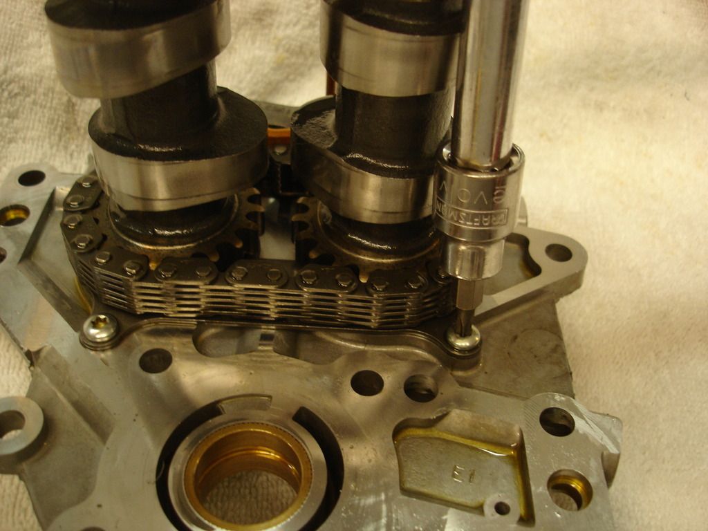
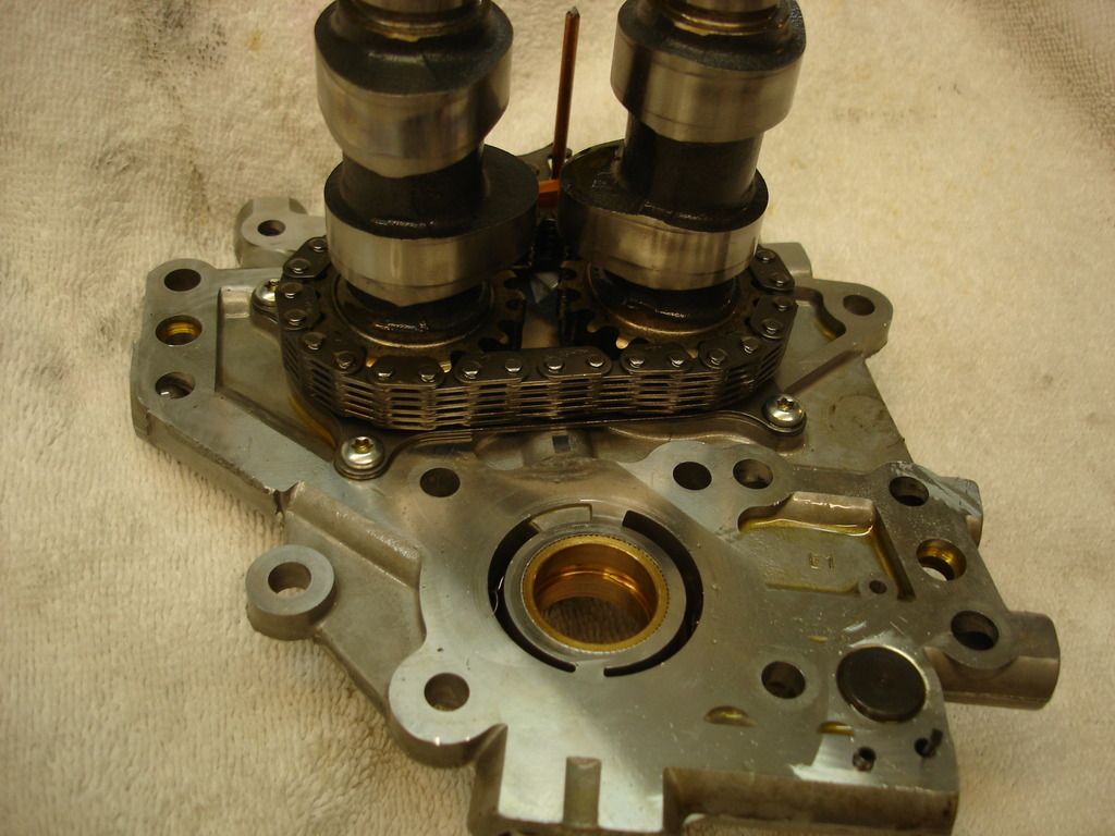
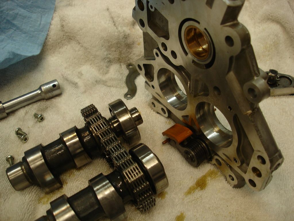
We have to remove the old cams and chain, so the bearing retainer has to come off. It is held in place with 4 torx screws.
Note: the large cam bearings are steel, mounted in an aluminum cam plate. When room temp, the bearings are a press fit. At operating temp. the aluminum expands more than the steel, so the bearings actually become a slip fit. We will use this fun physics fact to our advantage in a minute. For now, it is only important to know that the bearing retainer plate is necessary to hold the bearings in the plate when the engine is running.
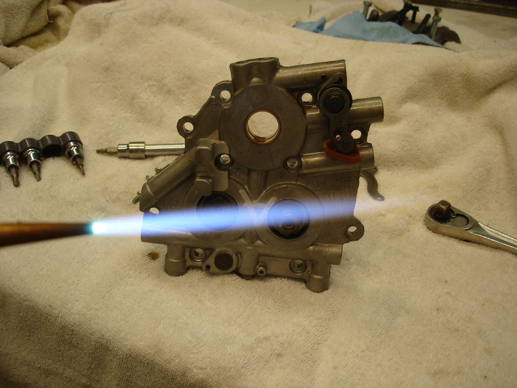
Now to remove the cams, with the bearings as a unit. Here I am using a torch to warm the cam plate. This is not the recommended way! I've done similar work many times and am comfortable with applying just enough heat. The cam plate, being aluminum, will be ruined if you get it over 400 degrees. If you are not comfortable using a torch, I recommend just putting the entire assembly in Mom's oven at 300 degrees for 20 minutes. That way you are assured to not damage the plate.
Once the plate is warmed to 300, use oven mits and turn it over...the cams fall right out! If you have to tap...don't worry about hurting the cams/bearings. We will be replacing them shortly.
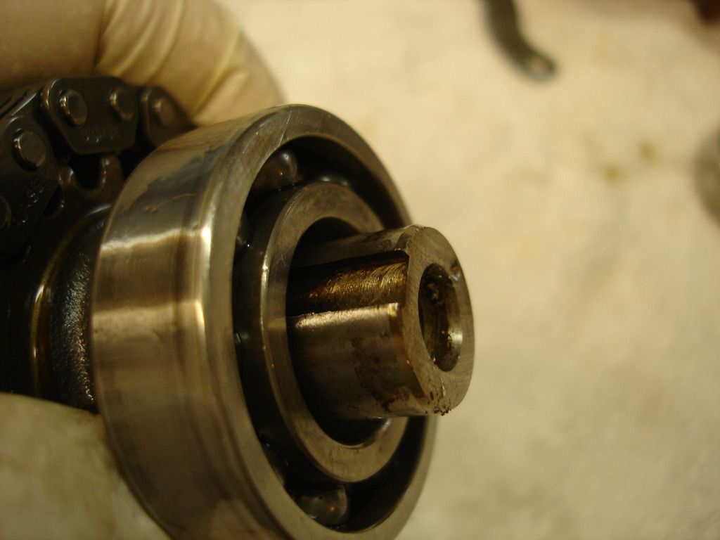
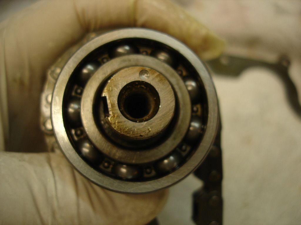
This is the outer end of the rear cam, which takes the sprocket to drive both cams. The keyway was only used for the first couple years of the TC, later changing to a sprocket to mount the sprocket. Yes, it is ironic.
Of note...the gear cam also uses a key to drive the cams! The difference is a chain drive tends to buck and slam parts around. The gear drive takes out all the hammering loads, so the key can live long and prosper.
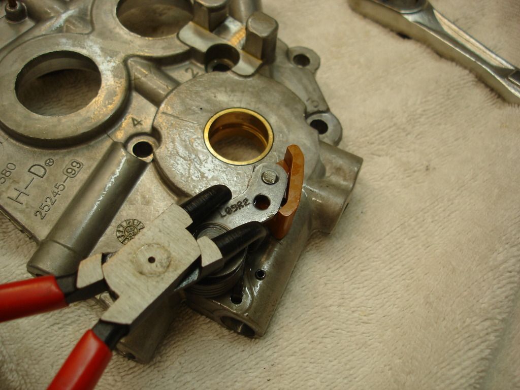
The final disassembly is to remove the spring tensioners...or the hydraulic ones if you have a newer bike. Here I am using snap ring pliers to twist the tensioner, remove the holding pin I had in place, and then unload the spring. There is a tool for this...I had no trouble add-libbing though.
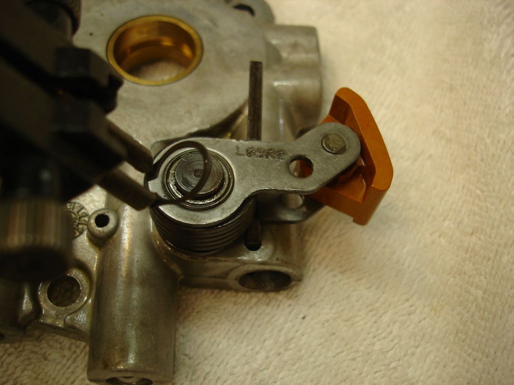
Once the spring is un-wound, you must remove the snap ring that holds the tensioner on its post.
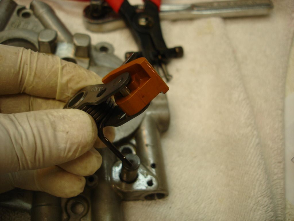
And the tensioner lifts right off. Good riddens!
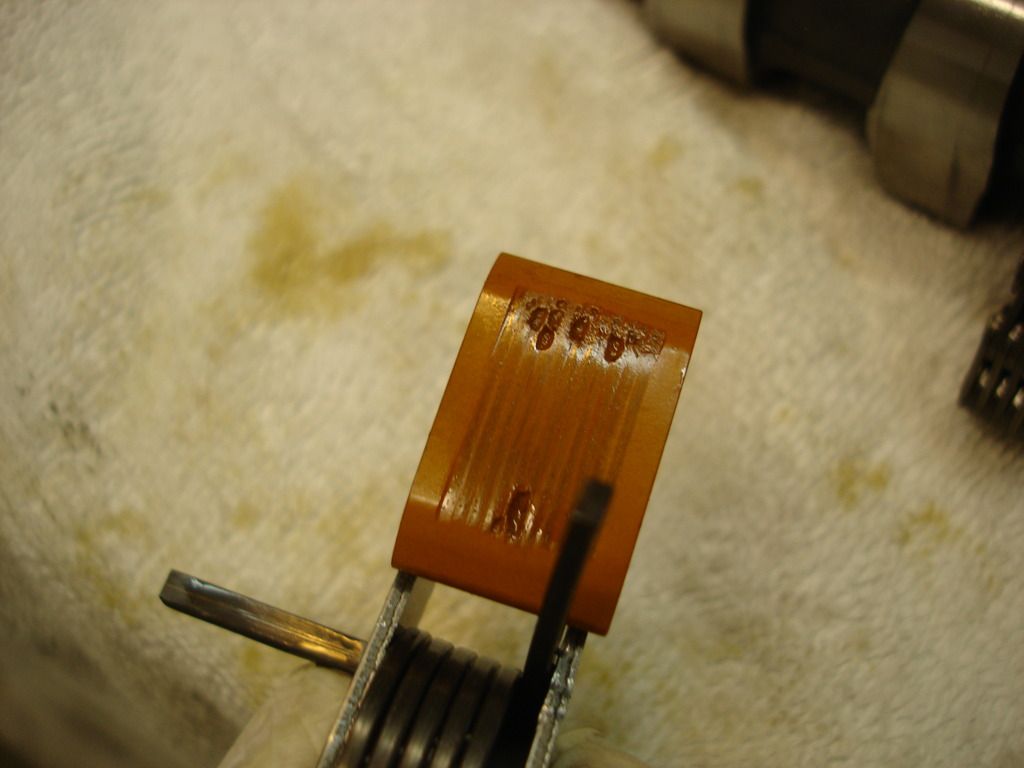
This is how my outer tensioner looked after 17 years, but only 3k miles. Those are pits in the plastic, which I see on every picture of a used tensioner. My tensioners had minimal wear, but the pits tell me that something in the plastic is affected by the oil additives. Interesting...but I no longer care after my mod!
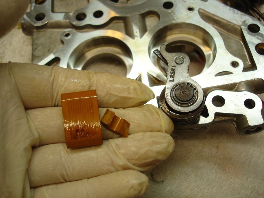
My home made tool snapped the inner tensioner as I was removing it. It took very little pressure to snap...showing how brittle these get over time.
S&S 510G gear cam kit...This is locked down by S&S, kinda like Apple does, where it's the same price everywhere...at $729. I did manage to find a slightly better deal on EBay, and the seller messed up the shipping, so I actually got it for $612.
Gasket set...HD 17045-99, only without the bearings that come in the OEM kit. JP Cycles for $55.
Needle bearing removal/install tool Ebay $88.
Dial indicator and base. I had these, but you can find them for roughly $50.
Then of course, you need typical tools, like sockets, torque wrenches and the like.
I do have a harbor freight press that I bought 25 years ago for $99. I see it's the same price even today! You can do the job without the press. It is easier if you have one, but I would not go buy one just for the cam job.
So, back to work...!


This is how the cam plate comes out following disassembly. Notice I was too cheap to buy the tensioner tools, so I used a short length of 1/8" welding rod to hold the tensioners back.

We have to remove the old cams and chain, so the bearing retainer has to come off. It is held in place with 4 torx screws.
Note: the large cam bearings are steel, mounted in an aluminum cam plate. When room temp, the bearings are a press fit. At operating temp. the aluminum expands more than the steel, so the bearings actually become a slip fit. We will use this fun physics fact to our advantage in a minute. For now, it is only important to know that the bearing retainer plate is necessary to hold the bearings in the plate when the engine is running.

Now to remove the cams, with the bearings as a unit. Here I am using a torch to warm the cam plate. This is not the recommended way! I've done similar work many times and am comfortable with applying just enough heat. The cam plate, being aluminum, will be ruined if you get it over 400 degrees. If you are not comfortable using a torch, I recommend just putting the entire assembly in Mom's oven at 300 degrees for 20 minutes. That way you are assured to not damage the plate.

Once the plate is warmed to 300, use oven mits and turn it over...the cams fall right out! If you have to tap...don't worry about hurting the cams/bearings. We will be replacing them shortly.


This is the outer end of the rear cam, which takes the sprocket to drive both cams. The keyway was only used for the first couple years of the TC, later changing to a sprocket to mount the sprocket. Yes, it is ironic.
Of note...the gear cam also uses a key to drive the cams! The difference is a chain drive tends to buck and slam parts around. The gear drive takes out all the hammering loads, so the key can live long and prosper.

The final disassembly is to remove the spring tensioners...or the hydraulic ones if you have a newer bike. Here I am using snap ring pliers to twist the tensioner, remove the holding pin I had in place, and then unload the spring. There is a tool for this...I had no trouble add-libbing though.

Once the spring is un-wound, you must remove the snap ring that holds the tensioner on its post.

And the tensioner lifts right off. Good riddens!

This is how my outer tensioner looked after 17 years, but only 3k miles. Those are pits in the plastic, which I see on every picture of a used tensioner. My tensioners had minimal wear, but the pits tell me that something in the plastic is affected by the oil additives. Interesting...but I no longer care after my mod!

My home made tool snapped the inner tensioner as I was removing it. It took very little pressure to snap...showing how brittle these get over time.
Last edited by CJD197; 05-20-2016 at 12:51 PM.
#33
05-20-2016 | 01:12 PM
Tourer
Joined: Jan 2016
Posts: 312
Likes: 6
From: charleston wv
Mine is 99 also I don't mind ordering tool to check run out but I'd hate to order gear drive cams then find out I have too much run out. I have approx 16k miles. I don't really want to wait to order cams as I don't want the bike down any longer than need be. Since I have the forged crank do you think I'll be within specs. Also I know having a press would be nice but you mentioned if you didn't have one you can do without could you explain to me how sorry for all the questions but I too have noticed noises and it just sounds kinda like chain noise but it stresses me out after seeing all the horror stories and just wanna ride stress free.
#35
05-20-2016 | 01:38 PM
Thread Starter
|
Tourer
Joined: Feb 2016
Posts: 309
Likes: 39
From: Southlake Texas

I love this pic! Here is the stock cam held next to the new S&S 510. Remember that the engine breaths during the "bump" on the cam. Compare the bumps and you can see how much extra breathing your engine gets after the cam swap! My original reason for the gear cam conversion was reliability. It's always nice to know you are adding performance too!

We now start the re-assembly. The instructions say to install the bearings in the plate, and then press the cams. I am going to do this backwards, for no other reason than I wanted to be different.
I will first press the bearings onto the cams.

Here I am using a socket to press ONLY on the inner race. You must never press, hammer, tap anywhere on a bearing that will load the *****. They will brinnel the races and have a short life if you do.
Now, if you do not have a press, you can accomplish this step by simply tapping the socket instead of pressing it. As long as you do not hit the outer race, you will not damage the bearing. If you tap, do place the end of the cam on something clean and not too hard.

The finished bearing/cam assembly. Notice the gear drive was pressed on to the cam too. That was done at S&S, so you don't have to do it.

Now, we put physics back to work. The cams go in Momma's freezer for 20 minutes, to get them good and cold...and shrunk!

The cam plate goes in Momma's oven, for 20 minutes at 300 degrees.


Bring them out together (using oven mitts again!) and the cams slip right in to the cam plate. Simple.
Notice the gears have double dots that must be aligned. These ensure the cams are timed correctly in relation to each other.

Here is how the outer side of the plate looks. Still hot!

S&S provides a new bearing retaining plate. Use the original screws and torque to 90 inch/lbs with blue locktite.

This is the oil pump. Notice there is an o-ring that should be replaced now. This is also the time you would install a new or high-volume oil pump if you plan on it. I didn't.

Notice no wear after 3k miles. If you see a lot of scarring, then metal has gotten into the pump...now would be the time to sort out the problem. Metal in the oil means something let go somewhere.

This is how the gerotor stack looks. The thicker rotor is the scavenge side of the pump that removes oil from the cam AND crank sides of the case. The thinner rotor is the pressure side that lubes virtually everything in the motor.
Note: Our TC is a dry sump system...as most are aware. This was developed for aircraft, that had thousands of HP through WW2 and beyond. It gets the oil away from the moving parts of the motor, so no power is lost whipping liquid all over the place. It's a very cool, very high performance system!

And the new o-ring goes in.

This is how the pump sits in relation to the cam plate. The snout of the crank goes completely through the oil pump and out the other side. There are 2 flats on the snout of the crank, and in the pump, that allow the crank to turn the pump. Just for your info...

Inside the lower rear of the cam case is another o-ring for the pump pressure outlet that should be replaced while we are there.

Now the pump goes on the crank snout. Here you have a good view of the flats on the crank/pump.

And the cams'plate go over everything. The cams fit into the Torrington bearings we replaced earlier, and the snout of the crank sticks out the bushing hole in the plate.

We will be using red locktite on the screws holding the plate in. Locktite is worthless unless you start with clean ans dry threads. Here I am using carb cleaner to get the oil and dirt out of every screw hole.

And then I use air to dry the threads. I will also wire brush the bolts and spray/dry them the same way.

Here is the finished cam plate assembly. There is a lot that goes into the installation:
First, the 4 bolts around the crank snout are NOT tightened until all the other bolts are in and torqued. There is a particular sequence that must be followed in tightening the bolts, and you work up the the final 96 inch/lbs in several stages to prevent warping anything. Remember 96 inch/lbs is only 8 ft/lbs...important NOT to confuse which you are dealing with!
Second, you slowly tighten the 4 inner bolts WHILE slowly turning the crank. These lock the oil pump into place, and turning the crank ensure the pump is centered before it gets locked down.

Key goes in the rear cam snout.

Now the rear gear goes on the rear cam. This is tightened to 35 ft/lbs. To prevent the gear from turning I am using a simple oil filter wrench.
The crank gear goes on the same, but torqued to 25 ft/lbs. I had to put the bike in 4th gear to hold the crank while torquing that gear.
There are several gear lash checks to perform as these gears go on. I was using both hands, so sorry, no picks. But, you first check the lash on the inner cam gears to make sure they never get completely tight with one another (.001-.003 lash desired). And then you check the outer drive gears for lash the same way. All that is in the instructions. The techs at S&S tell me it is about 1 in 20 bikes that have a lash issue.
If you have a lash problem, you have to call S&S and get and under/over sized gear to match the lash that you need. I, luckily, was one of the 19, so all was good!

Now the cam cover goes on with a new gasket.

The lifters go back in. Since mine only had 3k miles, I re-used my old lifters. In most cases you would want to replace the lifters with new ones at this point. If you do re-use, it is important to put the lifter in their original holes, in the original orientation. That's just good wrenching practice. You don't want to reverse any wear patterns that have started.
It's very hard to see, but on the right of the lifters in the pic, there is a steel rod laying against the lifters. This bar keeps the lifters rolling in alignment. Very important not to forget it.
Last edited by CJD197; 05-20-2016 at 02:38 PM.
The following users liked this post:
1999 Wide Glide (05-20-2016)
#37
05-20-2016 | 01:57 PM
Tourer
Joined: Jan 2016
Posts: 312
Likes: 6
From: charleston wv
thanks for the write up wish i had someone as knowledgeable here to help me do this. I feel like i can do it but would be nice to have someone watch over my shoulder and let me know if I'm doing it all right. I am still thinking about trying it though. I was thinking of going with andrews gear drive kit which is basically the same just diff cams but i dont think the gears come pressed on the cams. For someone new to motor work is this too much of a job would it be easier to go with hydraulic? Anyways thanks for the great write up and let us know what you think of those cams.
#38
05-20-2016 | 01:57 PM
Extreme HDF Member
Joined: Jun 2014
Posts: 11,448
Likes: 2,291
From: NW Ohio
#39
05-20-2016 | 01:58 PM
Thread Starter
|
Tourer
Joined: Feb 2016
Posts: 309
Likes: 39
From: Southlake Texas

The lifter covers go on with new o-rings and gaskets.

Now, the pushrods and tubes go in place, with new o-rings. At this point the top section is left slid down, so you can see the pushrods. Once again, if you re-use the pushrods, same rod in the same place and same orientation.
This is also where you would install adjustable pushrods if you so desire. The advantage of the adjustables is that you can do all the work we have done so far without having to remove your rocker covers on top of the engine. If you are using chains and tensioners...I personally would use adjustable pushrods, as it saves a good 2-3 hours in checking tensioners for wear.
In my case, I decided that, with the gear drive, I have no reason to go back into the cam case unless something breaks. If that happens I likely will have to take apart the tops anyway. So I went with the original, non-adjustable rods.

We won't do it yet, but these are the keepers that lock the tubes into place.

This is the top of the breather assembly that mounts onto each rocker assembly.
Talking performance, I was also very impressed with the Harley system for the breather. The round grey thing in the pick is a rubber flapper valve. Every time the 2 huge pistons go down in the jugs, a lot of air is displaced...it has to go somewhere. Well, it goes through this one-way valve into the air filter. Now, when the huge pistons go back up, the breather flapper closes, so no air can get back in the engine.
The result is that a vacuum is run in the TC engine crankcase. Less air is less resistance to the moving parts of the engine...and that is pretty cool! The Harley engine has the minimum oil and air possible to hinder performance.

The bottom of the breather valve has a filter, just to keep garbage from fouling the valve.

And this is how the breather goes back together on the rocker assembly. The 2 bolts for the breather also go through to the head, so they help hold the rocker plate down.

This is the oil passage coming up around the jug to the rocker assembly. It originally had a black o-ring. After 17 years, most of the o-rings I replaced were really for piece of mind, as the old ones looked just fine. This is the only exception. The heads get really hot...as in REALLY hot, when you sit a lights on a summer day. These o-rings were baked in place. I switched the generic black rings for this green nitrile ring. Nitrile is much more durable in high temp usage.

This is the rocker assembly ready to mount on the head. Look closely and you will see I screwed something up...somehow I got the big bolts reversed. There are 2 long and 2 short. Unlike me...make sure you put the short on the left and long on the right (close in the pic). I eventually figured it out as I was tightening the bolts...but if I had not noticed that one of the long bolts was bottoming in the hole before it was against the rocker assembly...I could have caused a bent assembly later.

I thought you would be interested in this pic. The manual tells you to remove the gas tank to remove the rocker covers. The problem with that is that there is a balance hose between the left and right sides of the tank that goes around the frame top. So...to remove the tank you have to drain it to remove the balance hose.
I just filled the tank and was too lazy to drain the whole thing. The tank is merely held on by 2 long bolts...one front and one rear. I pulled the long bolts and simply rocked the tank up enough to work on the heads. I used plenty of towels to keep the tank and frame from getting scratched while I moved the tank around.
If the tank was near empty I would recommend removing it...but just so you know, you don't absolutely have to remove it.

Here is a close-up of the rocker assembly on the head. The right screws are easy to reach. I had to use a crows foot on the bolts on the left side to get them torqued...the frame is too close to fit the torque wrench on the left. The rocker cover bolts are even worse on the left. Even with a crow foot, there is one bolt on each cover that cannot be torqued...there is no way to reach them. I had to use a 12 point box wrench and match the torque by feel as closely as possible. Fortunately, it is just a cover, so all it will do is leak if I got it wrong?!?
And...that is basically the whole job.
Last edited by CJD197; 05-20-2016 at 02:02 PM.
The following 2 users liked this post by CJD197:
1999 Wide Glide (05-20-2016),
bad tappets (05-22-2016)
#40
05-20-2016 | 02:24 PM
Thread Starter
|
Tourer
Joined: Feb 2016
Posts: 309
Likes: 39
From: Southlake Texas
OK, sorry, I'll try to catch up on questions...Let me know if I miss any...
If you note in the pic, the cam position sensor is located in the cam cover. As per the Harley manual, I left the sensor in the cover and just moved the cover out of the way...still attached by the sensor wire. So the cam cover is always down on the lower right as I worked. I wrapped it in a towel to keep from dinging it. The new S&S gears have the proper cam sensing tabs cast into the gears...so all works after you put it back together.
The first few years of the TC88 used the forged crank. Every article, and everyone I talked to about it said they have never seen the early forged cranks twist. So, if you have an early TC engine, there is almost no chance that the crank runout will be off.
If you have a newer engine...twisting a crank is possible, but still very unlikely unless you are in the habit of really banging your bike through full throttle shifts. It is still rare to twist a crank if you are running a stock cam.
Now...what I know everyone is waiting for...hows it run??
Unbelievable difference. I'm showing my age, but as a young gear head I didn't consider a bike or car fast unless it loped at idle. The idle on my bike sounds like a top fueler. Nice lope, and the exhaust note is about twice as loud as it was...even with the same thunderheader I was using before.
The S&S 510 is designed for 3k up on the torque curve. It's a bit less sure footed slipping the clutch on a start, but once moving above 1500rpm it feels just as good as the stock cam. Approaching 3k it comes on like the stock cam never could. I haven't had it out much yet...I'll update once I have. I did punch it one good time in 2nd gear and it pulled the front wheel off.
Running the stock carb, it sputters and pops winding down...but I love that sound. A long cammed engine always gets mad when you don't open it up, and that's exactly how the 510 acts.
For those wanting a more stock idle...the S&S 509 would be the cam to choose. It's designed for idle through mid range.
Best of all...all that clackity rattly sound is completely gone. When I listen very closely the cam box makes a "whirring" sound. Definitely better sounding than the rattly chains! Hey, just realized it's Friday...gotta go ride!
The following users liked this post:
Tommy C (05-20-2016)