This is a long overdue post, because it was the first mod I made to my Road King. I purchased a key fob remote and a waterproof switch online.
I programmed the remote to open my door then split open the case. I solder some 22 AWG wire to the contacts on the circuit board. I am sorry I have no pics of this, but it was real easy to do. Using a knife I made a small notch in the case for the wires to come out and snapped it back together. I used some self sealing silicone tape and wrapped around the top half of the remote to seal it for good measure. I used the tape because I will have to take it apart periodically to replace the batteries. I used heat shrink on the wires to protect them and clean up the look. Now I simply hung the remote under the handlebars in the front of the headlight nacelle using existing wires. You could zip tie it, but I didn't bother because it leaves plenty of slack to change batteries and I don't think it will go anywhere. Now I routed the wires through the handlebar clamp cover and through the existing wire clamps on the handle bars. You can internally wire this if desired and I will when I swap out the handlebars. Next remove the screws that hold the switches to the handlebar, I did the right side but there is also a blank on the left is you prefer. You will see two tiny screws that hold the switch blank on. Remove those and the blank is free to drill a hole. I used a 1/2" drill bit and made my hole then a dremel to slowly make a perfect fit. Take your time here, the object is to make the hole perfect so the switch will thread into the plastic and not require a nut. Once the fit is right you are almost done. Run the wire through between the clamps where the existing wires are. Then run the wires through the blank you just drilled out. Using the screw mounts in the switch insert a wire on each side and secure. This is a simple DC circuit so the polarity does not matter. Now thread the switch in the blank, which should be easy but snug if you took your time with the dremel and test fitting. Test the opener now, and if it works reassemble everything. Here are some pics of the finished product.
Last edited by Sw1; 07-18-2015 at 06:05 AM.
Reason: Adding pics
I think I bought the same momentary switch when I did mine on the SG. I put mine on the lower portion of my fairing switch panel. I wired it the same way you did, but bought a cheap garage door remote that wasn't waterproof and then plastidipped the whole thing.
When I had my King I bought the odometer button and put one on the opposite side of the dash.
Here is one I did a few years ago... Can be done with or without running it hot to the battery like I did.
Basically the same install as above, but this was on my Heritage.
--------------------------------------------------------------------------------------------------------------------------------
I wanted to install a garage door opener on the scoot, without giving the MoCo $130 bucks, so I used an existing visor mount model, and installed it in the dash. From the outside, there is no way to tell it's there.
Not counting the connectors and wire, which I already had, and the opener, which I already had, I have a total of 9 bucks, and 2 hours in this project.
This is a really simple project, if you trust yourself with a test light, a continuity tester and a soldering iron.
Here's how to do it:
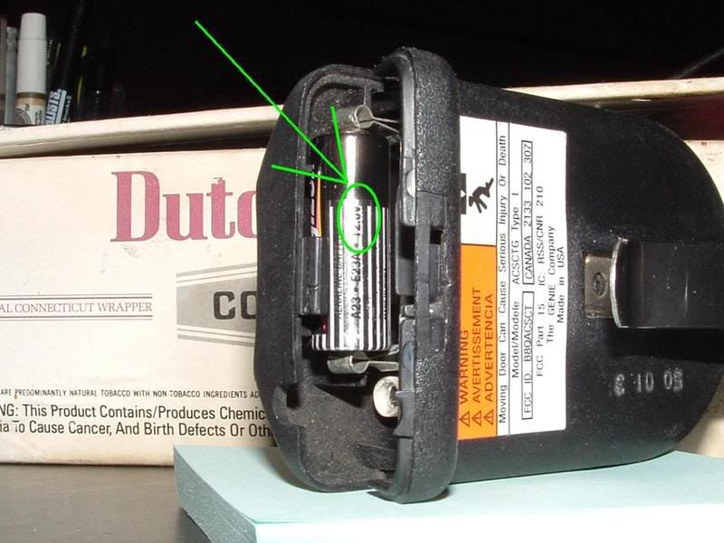
First, make sure you have a 12 volt unit. The battery will tell you how many volts. A 12v battery is near the diameter of a AA, but it is shorter.
__________________________________________________ __________________________________________
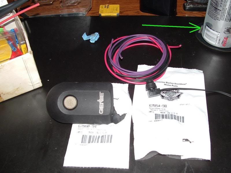
Second is the parts I needed.
HD# 67880-94 is the rubber boot.
HD# 67854-98 is the Speedometer Reset switch.
The opener, some wire, I used red for hot, black for ground, and purple for the switch.
A 3M Quick Connect, for the hot lead.
Shrink tube and heat-shrink connectors, I like waterproof.
And most important, if you follow the green arrow... Diet Coke.
__________________________________________________ __________________________________________
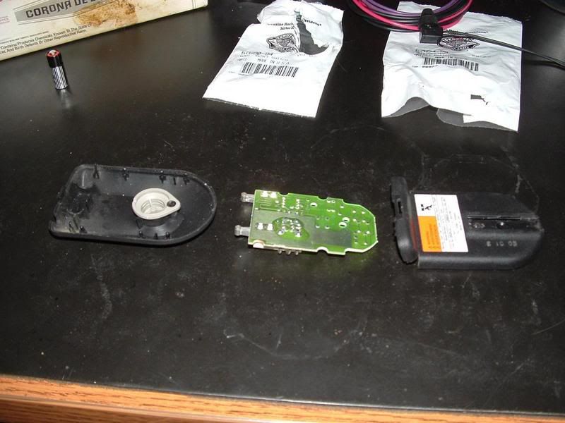
This is what it looks like, when you take it apart.
__________________________________________________ __________________________________________
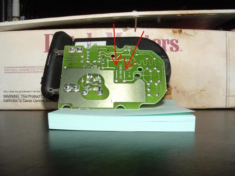
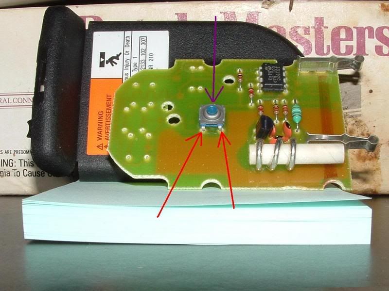
This is the bottom of your circuit board. The red arrows point to the back of the switch. Note there are 2 poles to each side of the switch.
__________________________________________________ __________________________________________
This is the top of your circuit board. The purple arrow points to the switch, and the red arrows point to 2 of the poles.
__________________________________________________ __________________________________________
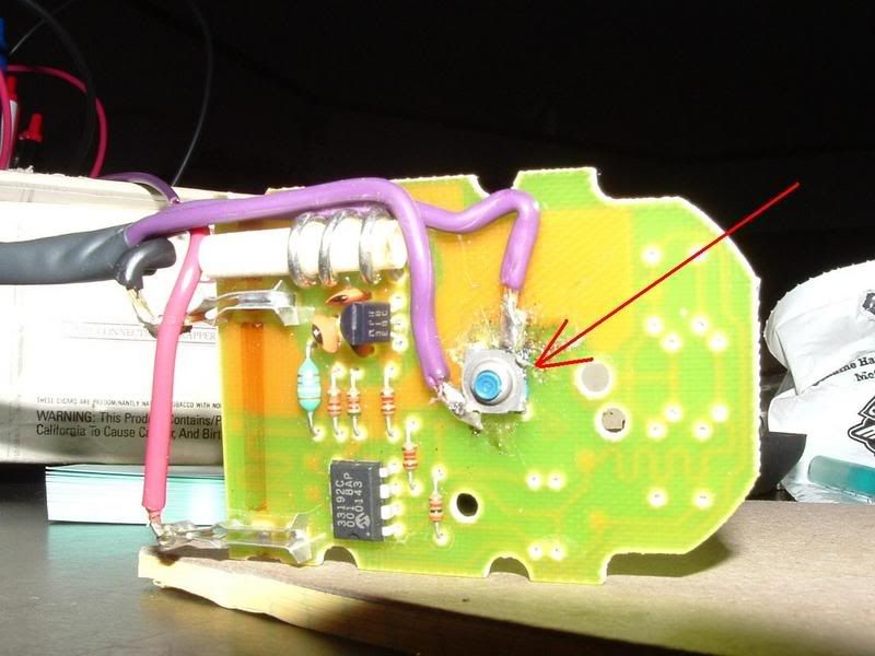
Here it is with all of the wires soldered in place. Note where the red arrow is I bent the corner of the switch up. I used a continuity tester to be sure I did not cross the switch, and found I had, so I bent it up a bit.
Be sure you know which pole is hot and which is ground for your power.
__________________________________________________ __________________________________________
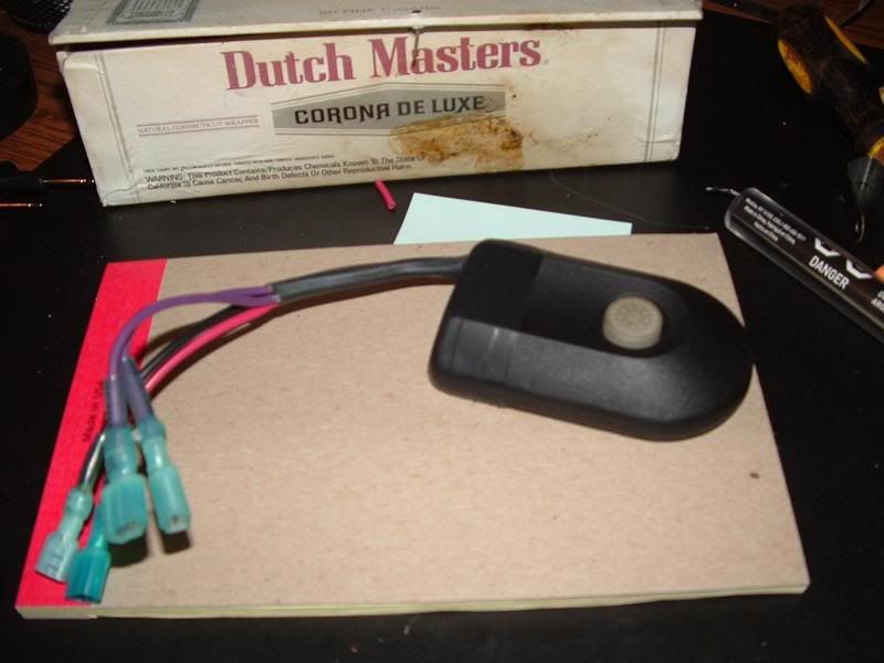
Here it is finished, and reassembled.
__________________________________________________ __________________________________________
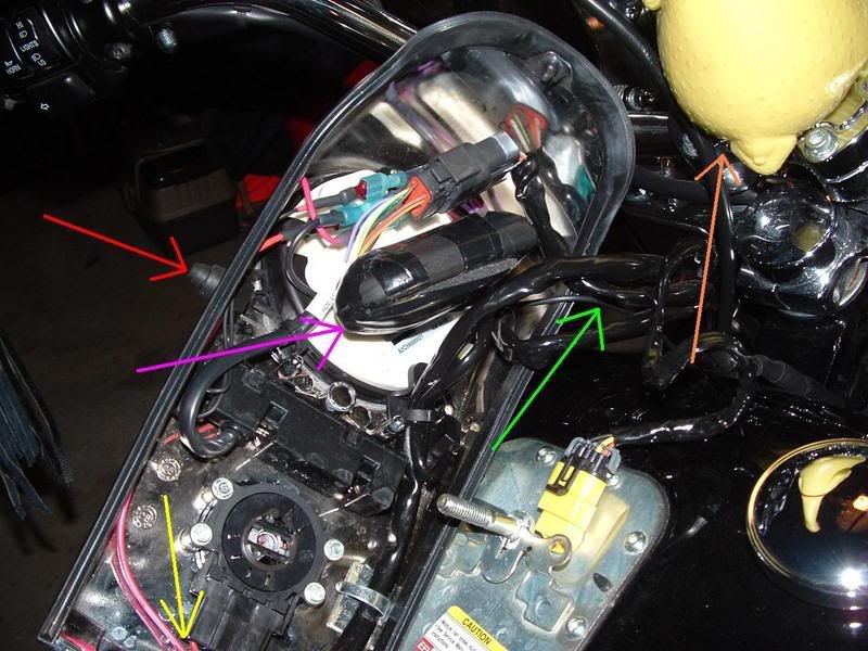
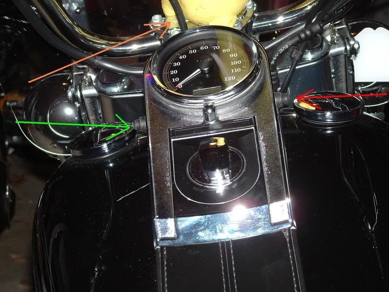
In the dash...
Yellow arrow: Hot lead to the accessory lead under the ignition switch.
Green arrow: Ground run to the bolt at the top of my engine guard.
Red arrow: New switch installed.
Purple arrow: I wrapped some weatherproof foam and tape around the unit.
Orange arrow: Chickie's Butt.
__________________________________________________ __________________________________________
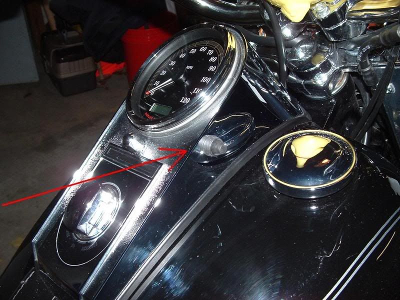
Here is the new switch installed...
__________________________________________________ __________________________________________
And here it is once again, finished
Green arrow: Speedometer/Clock/Odometer reset
Red arrow: Garage Door Opener
Orange arrow: Chickie's Butt
__________________________________________________ __________________________________________
I've got nearly the same key fob remote. Just keep it on a ring with security fob, clipped to belt loop. I can just reach down without even looking and open door.
Once in my new house, may play with a permanent install.... like yours.
I used an extra visor mount. Removed the clip from the back of it. Stuck on some 3M double sided mounting tape. Mounted to the inside of front lower storage pocket.

 07-18-2015, 05:58 AM