
Need some electrical help
#1
 01-29-2015 | 06:20 PM
Thread Starter
|
Road Warrior
Joined: Jan 2010
Posts: 1,644
Likes: 30
From: Canton, Ohio
I bought the kit to add Aux switches to the left side of the fork lock on my '15 SERGU. http://www.harley-davidson.com/store...-fairing-mount
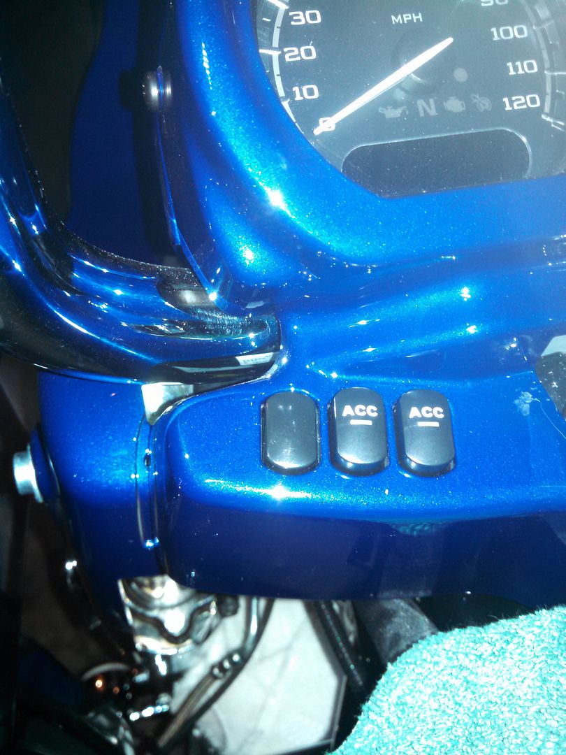
It came with the switch block, the harness and a few zip ties and connectors. I got the switch mounted without issue and there's a harness right under the cover that leads back to a connector under the left side cover per the instructions.
Here's where it gets interesting. There are two unused plugs underneath the fuse block in that area. See pix below from the Supplement manual
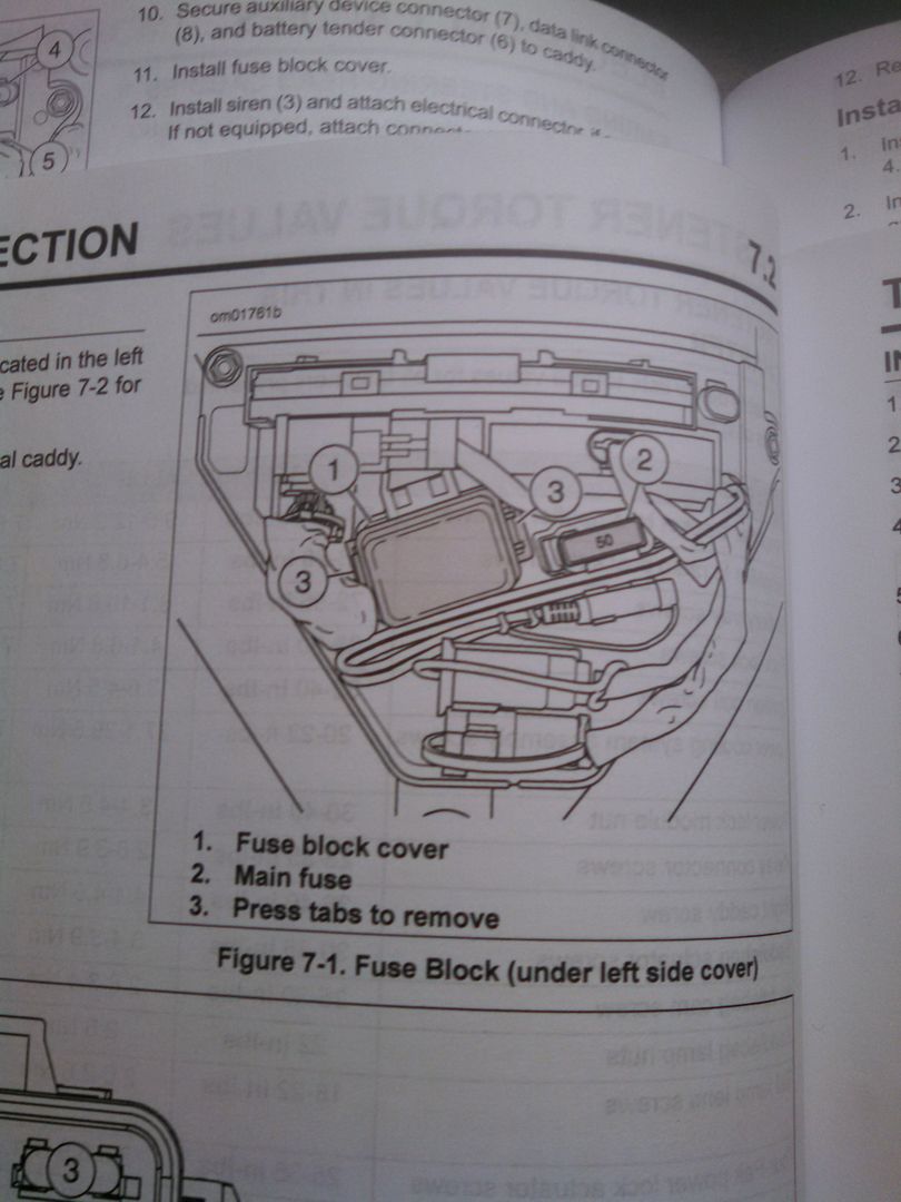
For the life of me I can't find which plug is supposed to be what in the FLTRUSE supplement manual. There's no complete breakdown pix in that book of the left side cover anywhere.
I DID find in the regular service manual a pix of what I'm looking for....
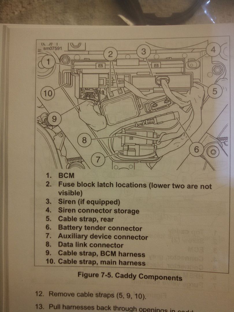
Now it get's worse... according to the above pix plug #7 is the aux plug and plug #8 is a Data Link connector...
The plug on the harness that came in the kit fits plug #8, NOT plug #7.
So anyway, I plugged in the harness to #8 and started checking for voltage on the outputs of the two aux pigtails (one for each switch in the dash) and they work like they should. I even hear the relay click when you hit one of the two switches on the dash.
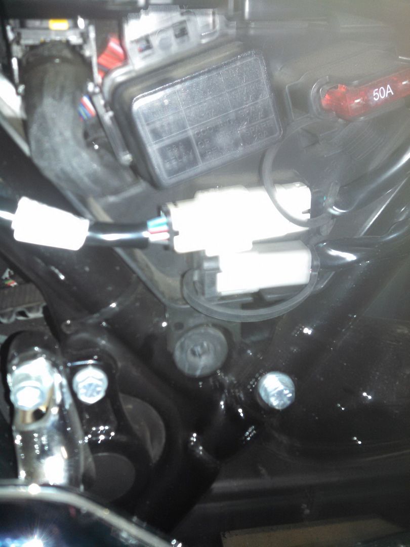
Here's a pix of the harness.
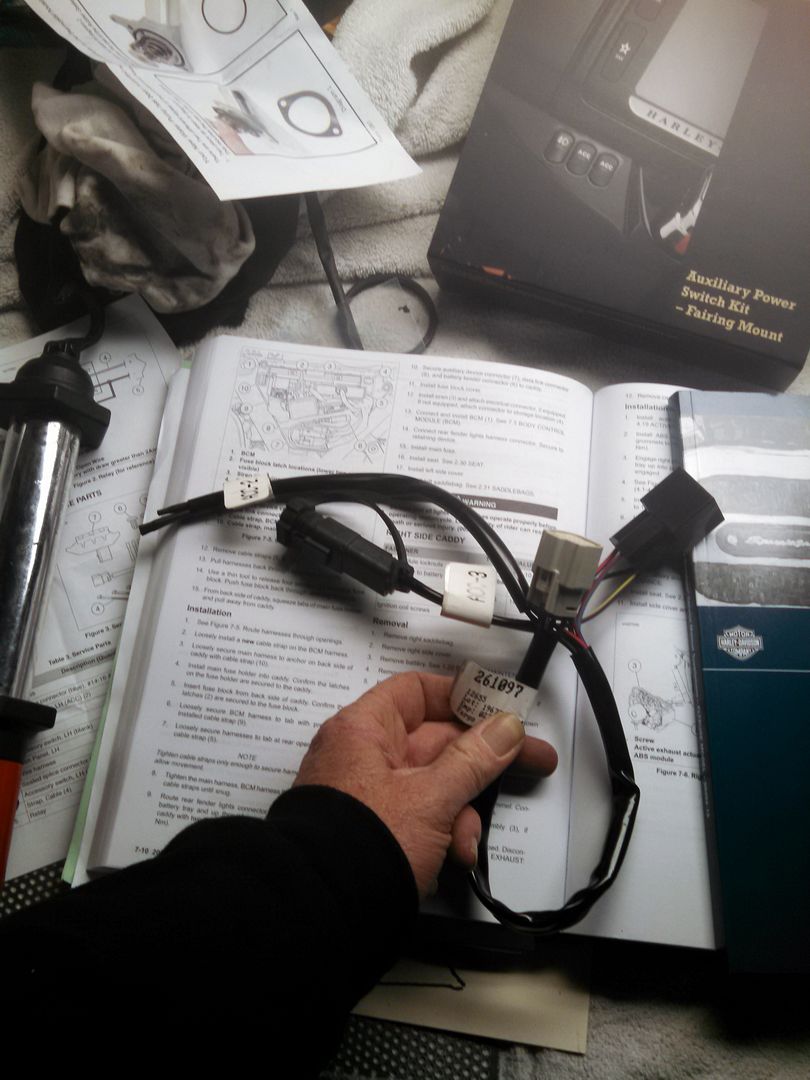
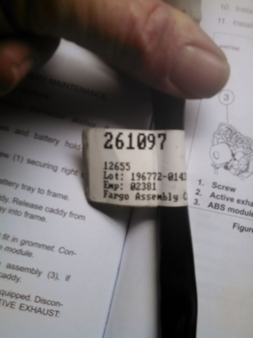
and the part number of the harness
Is there any way at all that the pix from the regular service manual is labeled incorrectly? Do you think the CVO wiring is that much different from a standard bike?
One more thing. Now I have to try to find a way to get that harness to fit somewhere. It sure as hell isn't going to fit behind that side cover.

It came with the switch block, the harness and a few zip ties and connectors. I got the switch mounted without issue and there's a harness right under the cover that leads back to a connector under the left side cover per the instructions.
Here's where it gets interesting. There are two unused plugs underneath the fuse block in that area. See pix below from the Supplement manual

For the life of me I can't find which plug is supposed to be what in the FLTRUSE supplement manual. There's no complete breakdown pix in that book of the left side cover anywhere.
I DID find in the regular service manual a pix of what I'm looking for....

Now it get's worse... according to the above pix plug #7 is the aux plug and plug #8 is a Data Link connector...
The plug on the harness that came in the kit fits plug #8, NOT plug #7.

So anyway, I plugged in the harness to #8 and started checking for voltage on the outputs of the two aux pigtails (one for each switch in the dash) and they work like they should. I even hear the relay click when you hit one of the two switches on the dash.
Here's a pix of the harness.

and the part number of the harness

Is there any way at all that the pix from the regular service manual is labeled incorrectly? Do you think the CVO wiring is that much different from a standard bike?
One more thing. Now I have to try to find a way to get that harness to fit somewhere. It sure as hell isn't going to fit behind that side cover.
#2
01-29-2015 | 07:16 PM

Road Warrior
Joined: Jul 2013
Posts: 1,624
Likes: 12
From: Fort Worth
Could it have been that the connectors were just mounted in the wrong spots? I have a PV plugged in to my datalink connector and it's in the bottom spot and the aux connector is on the top. I have a 2015 CVO Limited.
ETA: Oh, I just looked at the diagram picture above. Yup, I think the book is mislabeled or you and me, the assembly line stuck them on the wrong mounting track.
ETA: Oh, I just looked at the diagram picture above. Yup, I think the book is mislabeled or you and me, the assembly line stuck them on the wrong mounting track.
#3
01-29-2015 | 07:30 PM
Supporter
Joined: Mar 2011
Posts: 587
Likes: 1
From: Ga.
What are you going to connect to the Aux cable? If you are not actually going to connect anything to it at this time, then you can just disconnect the cable and put it in a safe place at the house. I know that I installed this on mine the day I bought the bike, but did not have anything to actually use it for at the time, so I didn't connect the cable, only the switches to get rid of the blank buttons.
For the routing, disconnect the cable and pull out the one in the holder and then look at the top right of the box, you should see the spot that you will put the connector thru and then re-connect the cable and zip tie to the frame or such, under the seat.
FinalShot already answered part of the question, just to add to his, yes it's the correct connection, wrong in the book.
#4
01-29-2015 | 07:33 PM
Thread Starter
|
Road Warrior
Joined: Jan 2010
Posts: 1,644
Likes: 30
From: Canton, Ohio
Could it have been that the connectors were just mounted in the wrong spots? I have a PV plugged in to my datalink connector and it's in the bottom spot and the aux connector is on the top. I have a 2015 CVO Limited.
ETA: Oh, I just looked at the diagram picture above. Yup, I think the book is mislabeled or you and me, the assembly line stuck them on the wrong mounting track.
ETA: Oh, I just looked at the diagram picture above. Yup, I think the book is mislabeled or you and me, the assembly line stuck them on the wrong mounting track.
#5
01-29-2015 | 07:36 PM
Thread Starter
|
Road Warrior
Joined: Jan 2010
Posts: 1,644
Likes: 30
From: Canton, Ohio
What are you going to connect to the Aux cable? If you are not actually going to connect anything to it at this time, then you can just disconnect the cable and put it in a safe place at the house. I know that I installed this on mine the day I bought the bike, but did not have anything to actually use it for at the time, so I didn't connect the cable, only the switches to get rid of the blank buttons.
For the routing, disconnect the cable and pull out the one in the holder and then look at the top right of the box, you should see the spot that you will put the connector thru and then re-connect the cable and zip tie to the frame or such, under the seat.
FinalShot already answered part of the question, just to add to his, yes it's the correct connection, wrong in the book.
For the routing, disconnect the cable and pull out the one in the holder and then look at the top right of the box, you should see the spot that you will put the connector thru and then re-connect the cable and zip tie to the frame or such, under the seat.
FinalShot already answered part of the question, just to add to his, yes it's the correct connection, wrong in the book.
Just some lights. I have a set of caliper mounted driving lights I made that I want to have switched. I also have some LED lights to go all over the bike. New canbus system is not something I'm willing to tap into a hot lead just anywhere.
Will have to explore that moving the plug. Lighting in my garage sucks and it was getting close to dinner time so I stopped for the night.
#6
01-29-2015 | 10:31 PM
Road Warrior
Joined: Jul 2013
Posts: 1,624
Likes: 12
From: Fort Worth
#7
01-30-2015 | 05:12 AM
Thread Starter
|
Road Warrior
Joined: Jan 2010
Posts: 1,644
Likes: 30
From: Canton, Ohio

The rest of the LED light I bought on the RG forum from a guy named Paul. Very similar to what I did on my last bike but I didn't spend 12 hours custom making the strips this time. There's actually more lights than what's in the pix but I didn't have them all hooked up yet.

Trending Topics
#8
01-30-2015 | 01:56 PM
Road Warrior
Joined: Jul 2013
Posts: 1,624
Likes: 12
From: Fort Worth
Caliper mounted home made driving lights. Dyna turn signals that have been gutted and LED inserts installed in them. A couple of swivel mounts and bolted them in using the lower caliper bolt. Pix from my old bike.
The rest of the LED light I bought on the RG forum from a guy named Paul. Very similar to what I did on my last bike but I didn't spend 12 hours custom making the strips this time. There's actually more lights than what's in the pix but I didn't have them all hooked up yet.
The rest of the LED light I bought on the RG forum from a guy named Paul. Very similar to what I did on my last bike but I didn't spend 12 hours custom making the strips this time. There's actually more lights than what's in the pix but I didn't have them all hooked up yet.
#9
01-30-2015 | 06:57 PM

Stellar HDF Member
Joined: Aug 2008
Posts: 2,060
Likes: 157
Could it have been that the connectors were just mounted in the wrong spots? I have a PV plugged in to my datalink connector and it's in the bottom spot and the aux connector is on the top. I have a 2015 CVO Limited.
ETA: Oh, I just looked at the diagram picture above. Yup, I think the book is mislabeled or you and me, the assembly line stuck them on the wrong mounting track.
ETA: Oh, I just looked at the diagram picture above. Yup, I think the book is mislabeled or you and me, the assembly line stuck them on the wrong mounting track.


Thread
Thread Starter
Forum
Replies
Last Post
Jethro
2014-2023 Touring Models
4
07-27-2017 10:41 PM
fiddypal
Milwaukee Eight (M8)
17
05-29-2017 07:47 AM